Valve Assembly to Transfer Plate Assemble
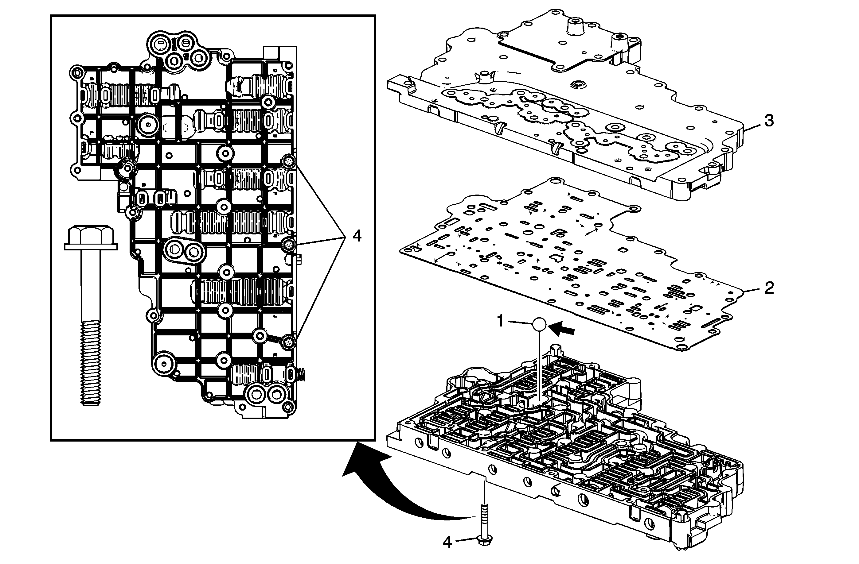
Callout | Component Name |
|---|---|
1 | A/Trans Fluid Pump Ball Check Valve Tip |
2 | Control Valve Body Spacer (w/Gasket) Plate Assembly Caution: Do not use the old spacer plate. Install a NEW spacer plate. Reusing an old spacer plate may cause internal transmission leaks and transmission damage. |
3 | Control Valve Channel Plate Tip |
4 | Control Valve Channel Plate Bolt M6 x1.0 x 35 (Qty: 3) Tip |
Filter Plate Installation
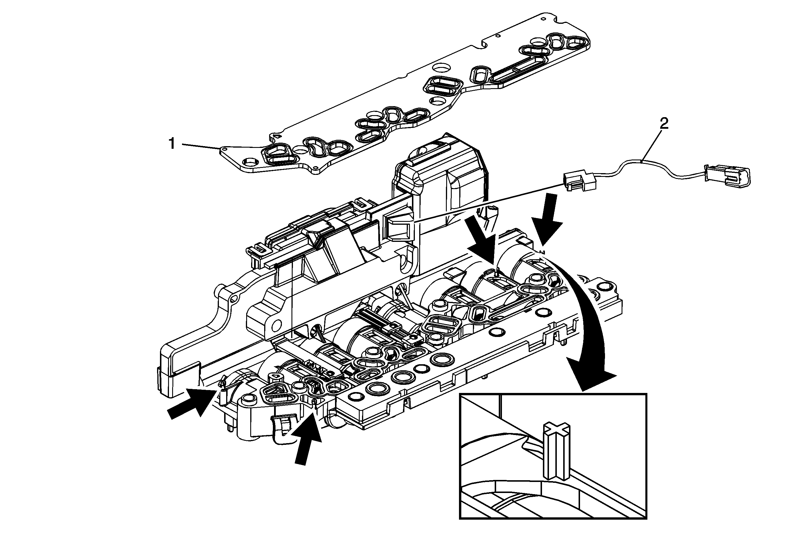
Callout | Component Name |
|---|---|
1 | Control Valve Channel Plate Spacer Plate Gasket Caution: Use care when handling the control valve body assembly. If dropped, damage to the control solenoid valve body assembly internal components, including the transmission control module (TCM), may result. Caution: Carefully feed temp sensor and resolver connector thru case opening or damage may occur. Tip |
2 | A/Trans Wiring Harness Assembly |
Control Solenoid (w/Body and TCM) Valve Installation
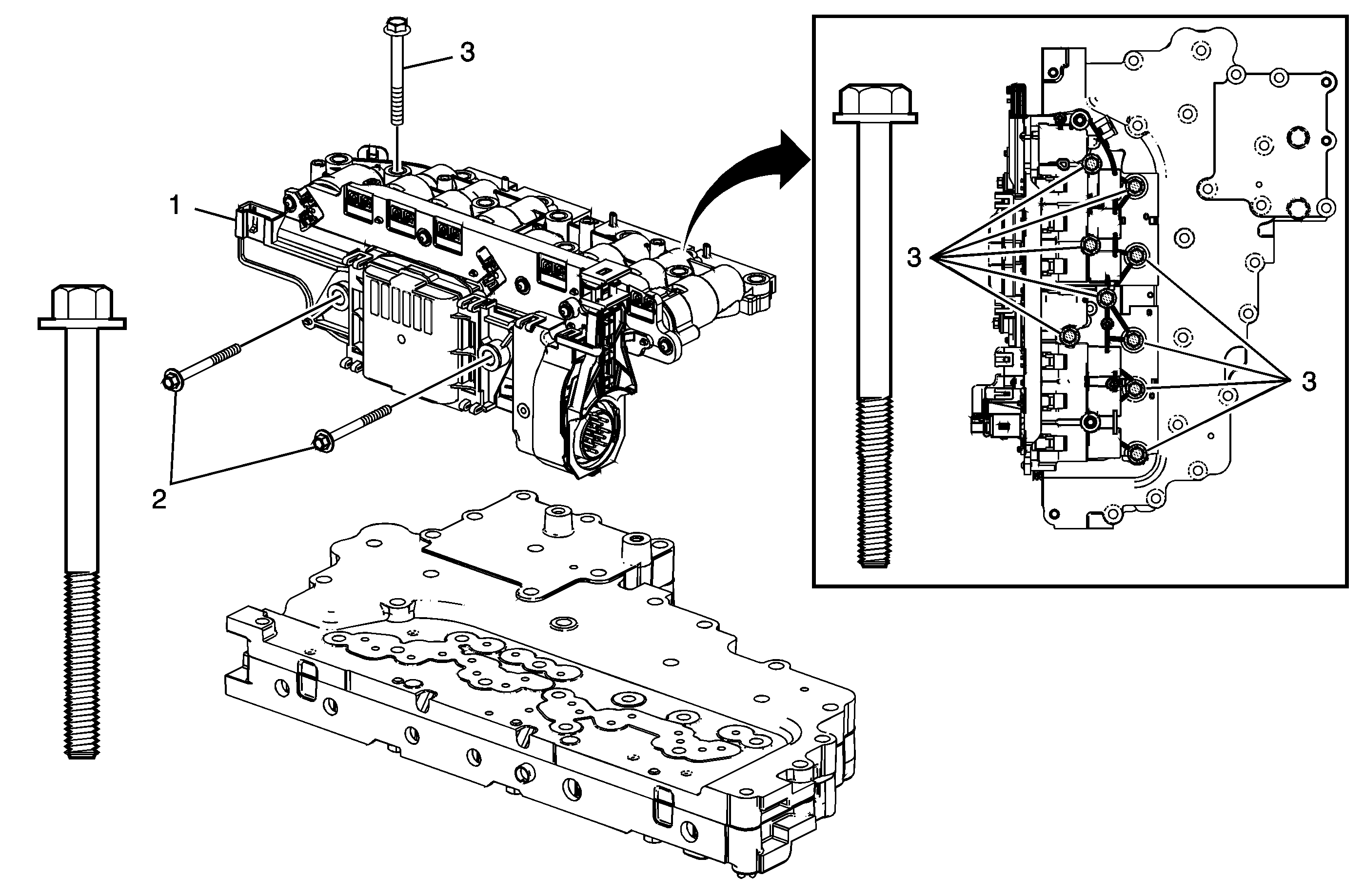
Callout | Component Name |
|---|---|
1 | Control Solenoid (w/Body and TCM) Valve Assembly Tip |
2 | Control Solenoid Valve Heat Sink (w/Body and TCM) Bolt M5 x.8 x 53 (Qty: 2) Tip |
3 | Control Valve Lower Body Bolt M6 x1.0 x 55 (Qty: 9) Tip |
Control Valve Body, Upper and Lower Assembly
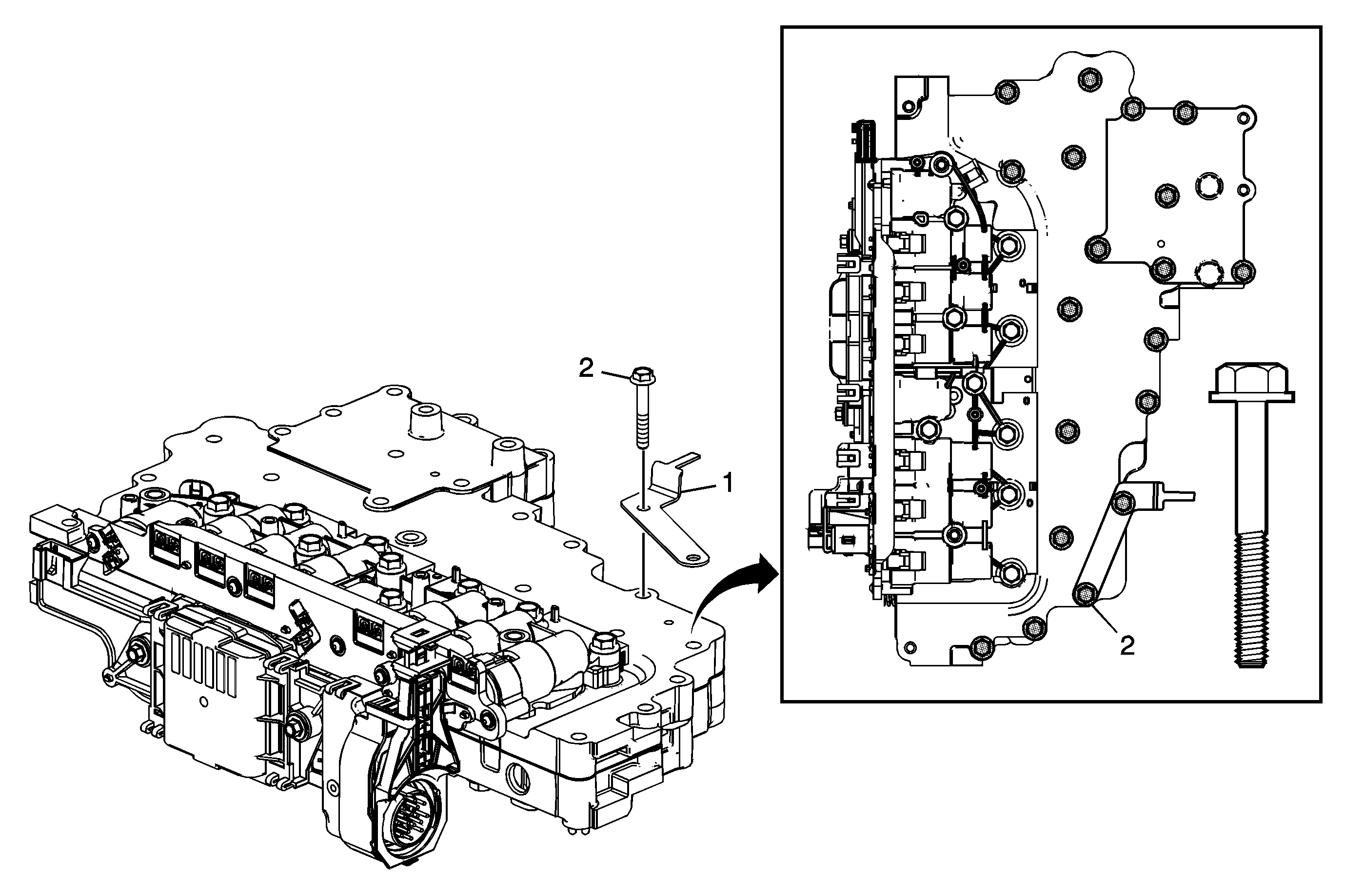
Callout | Component Name |
|---|---|
|
Caution: Bolt torque sequencing is critical to the proper function of the control solenoid valve assembly. Failure to follow the required sequencing may result in transmission malfunction. | |
1 | A/Trans Manual Shift Shaft Postion Switch Assembly Bracket |
2 | Control Valve Channel Plate Bolts M6 x1.0 x 35 (Qty: 19) Tip |
Valve Body, Control Solenoid Torque Sequence
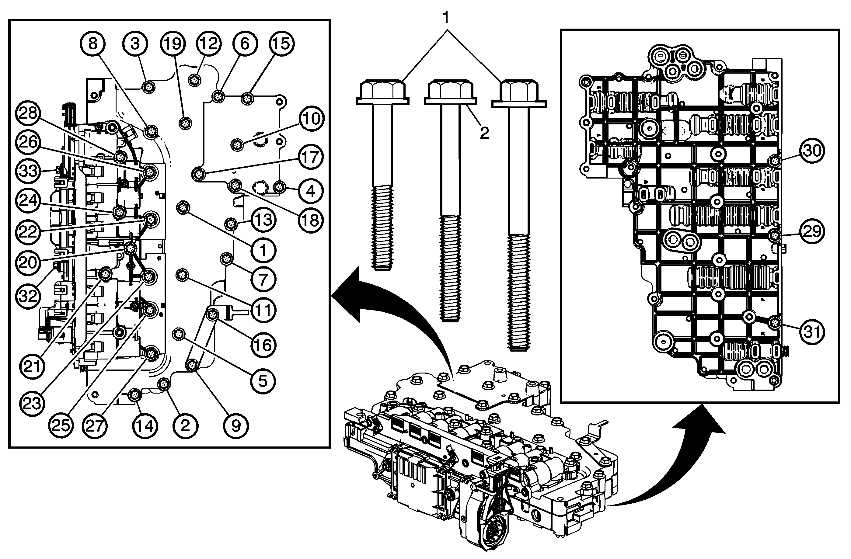
Callout | Component Name |
|---|---|
|
Caution: Bolt torque sequencing is critical to the proper function of the control solenoid valve assembly. Failure to follow the required sequencing may result in transmission malfunction. Preliminary ProcedureThe 2 heat sink bolts must be tightened last. | |
1 | Control Valve Body Bolts M6 x1.0 x 55 (Qty: 31) Caution: Refer to Fastener Caution in the Preface section. ProcedureTighten all 31 bolts in the sequence shown. Tighten |
2 | Control Solenoid Valve Heat Sink (w/Body and TCM) Bolt M5 x.8 x 53 (Qty: 2). Tip Tighten |
Control Bodies Contact Gap Inspection
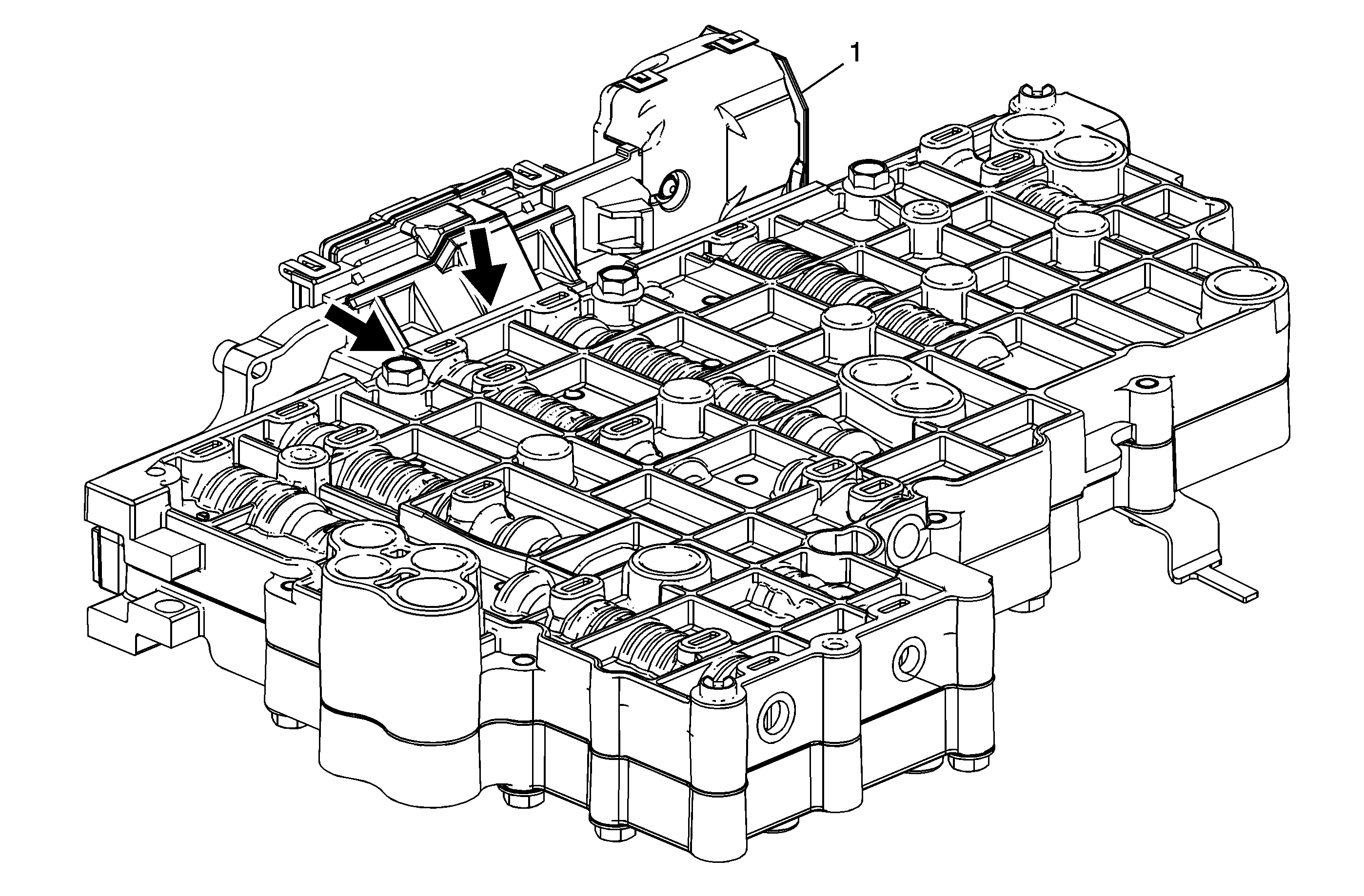
Callout | Component Name |
|---|---|
1 | Control Solenoid (w/Body and TCM) Valve Assembly Tip |
