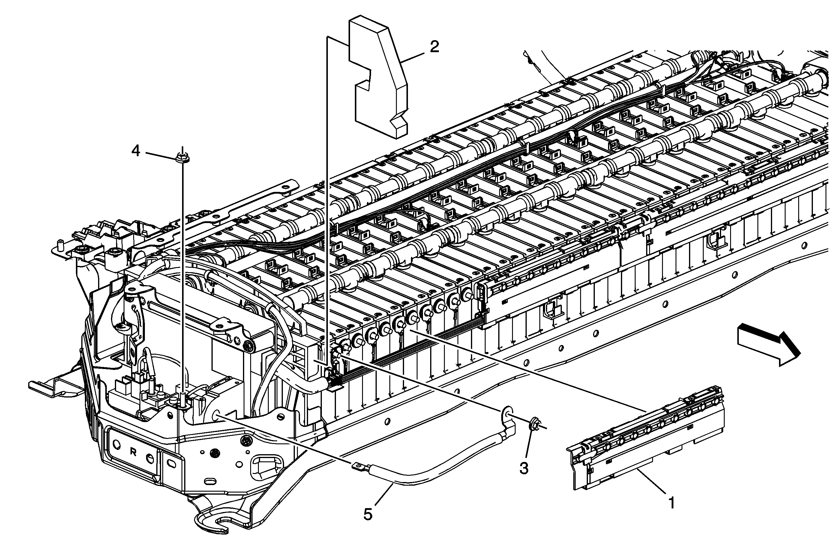
Callout
| Component Name
|
|
Danger: Always perform the High Voltage Disabling procedure prior to servicing any High
Voltage component or connection. Personal Protection Equipment (PPE) and proper procedures must be followed.
The High Voltage Disabling procedure will perform the following tasks:
| • | Identify how to disable high voltage. |
| • | Identify how to test for the presence of high voltage. |
| • | Identify condition under which high voltage is always present and personal protection equipment (PPE) and proper procedures must be followed. |
Preliminary Procedures
- Disable the high voltage at the drive motor generator battery. Refer to
High Voltage Disabling.
- Remove the upper cover and right cover. Refer to
Drive Motor Battery Case Upper Cover, Front Cover, and Right Side Cover Replacement.
|
1
| Drive Motor Battery Cell Terminal Assembly Cover
|
2
| Drive Motor Battery Cooling Air Outlet Duct Seal
|
3
| Drive Motor Battery Cable Terminal Nut
Caution: Refer to Fastener Caution in the Preface section.
Tip
Always use the correct tightening sequence and specifications when installing fasteners in order to avoid damage to parts and systems.
Tighten
5 N·m (44 lb in) |
4
| Drive Motor Battery Cable Assembly Nut
Tip
Always use the correct tightening sequence and specifications when installing fasteners in order to avoid damage to parts and systems.
Tighten
5 N·m (44 lb in) |
5
| Drive Motor Battery Positive Relay Cable Assembly
ProcedureAfter the cable assembly has been replaced and the re-assembly of the drive motor generator battery, enable the HV system. Refer to
High Voltage Enabling.
|

