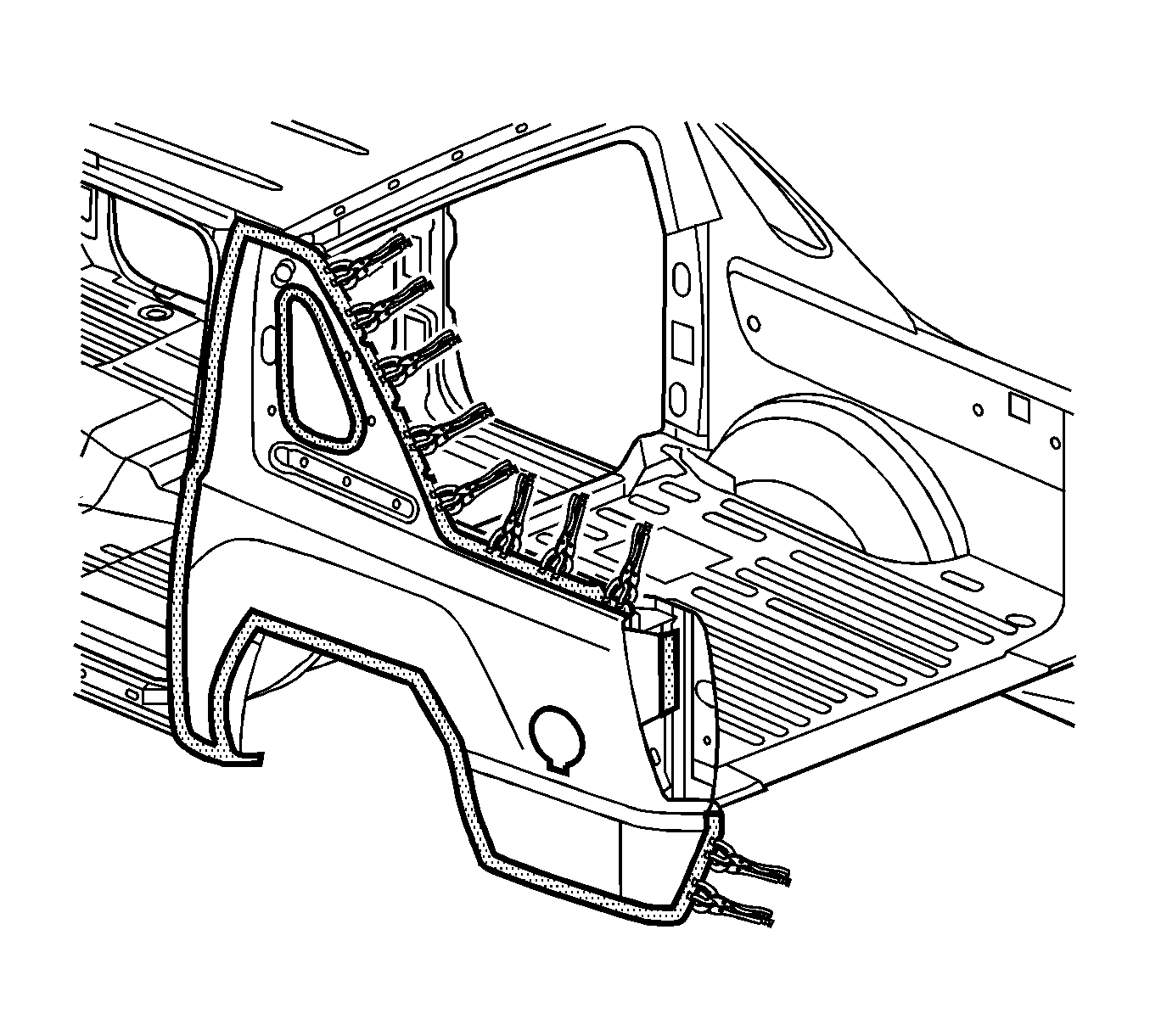
Quarter Outer Panel Sectioning Utility
Removal Procedure
Warning: Refer to Approved Equipment for Collision Repair Warning in the Preface section.
Warning: Refer to Glass and Sheet Metal Handling Warning in the Preface section.
Warning: Refer to Collision Sectioning Warning in the Preface section.
- Disable the SIR system. Refer to SIR Disabling and Enabling.
- Disconnect the negative battery cable. Refer to Battery Negative Cable Disconnection and Connection.
- Remove all related panels and components.
- Repair as much of the damage as possible to factory specifications. Refer to Dimensions - Body.
- Note the location and remove the sealers and anti-corrosion materials from the repair area, as necessary. Refer to Anti-Corrosion Treatment and Repair.
- Cut the panel in the locations where sectioning is to be performed.
- Locate and drill out all factory welds. Note the number and location of the welds for installation of the service part.
- Remove the damaged quarter panel
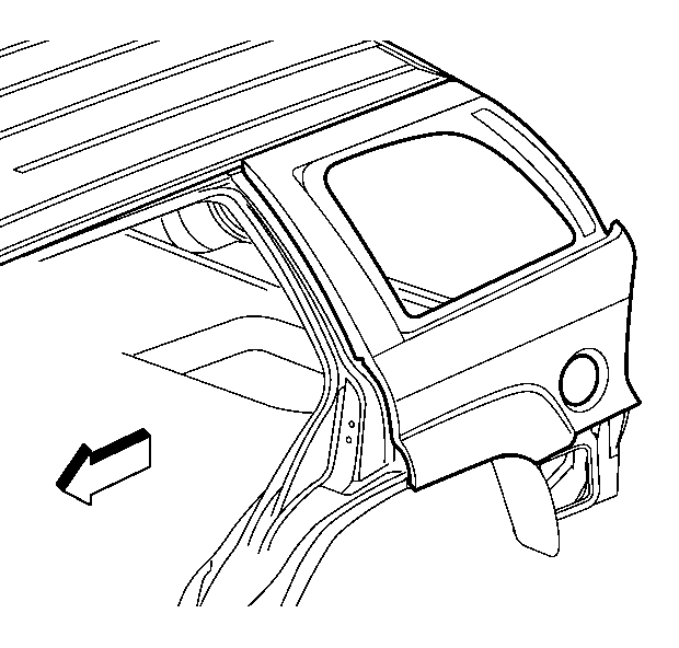
Note: The quarter panel can be serviced as a complete panel or sectioned. When the complete panel replacement is performed, the roof panel must be removed.
Warning: Refer to Foam Sound Deadeners Warning in the Preface section.
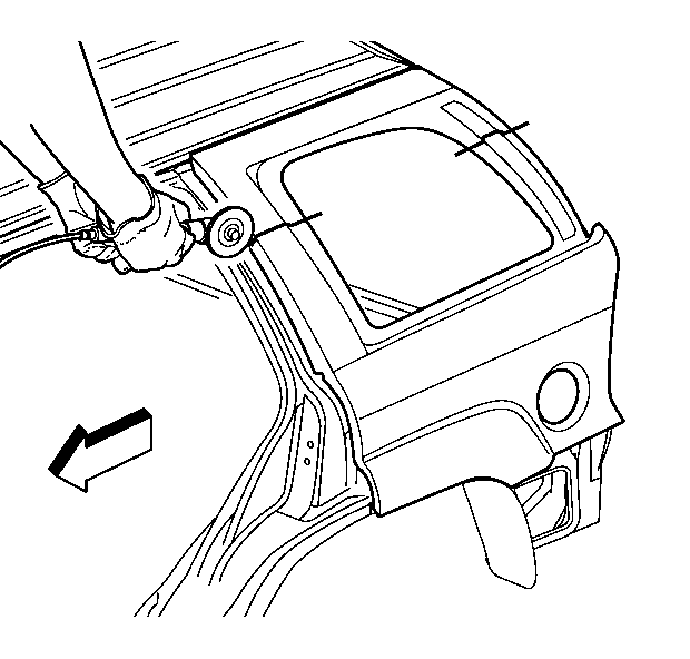
Note: Do not damage any inner panels or reinforcements.
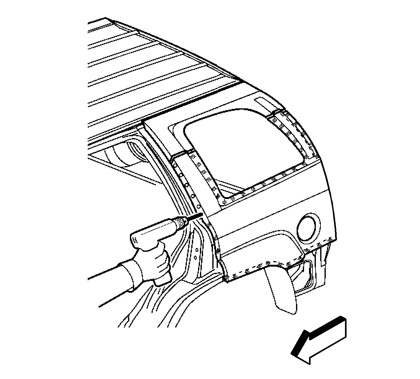
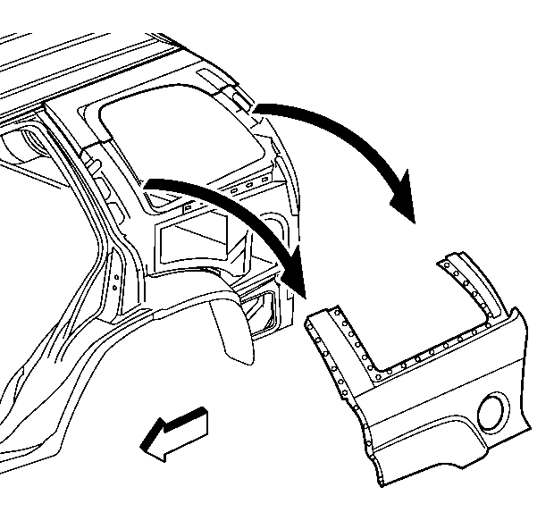
Installation Procedure
- Cut the replacement quarter panel in corresponding locations to fit the remaining original panel. The sectioning joint should be trimmed to allow a gap of 1½ times the metal thickness at the sectioning joint.
- Create a 50 mm (2 in) (A) backing plate from the unused portion of the service part. Trim the backing plate as necessary to fit behind the sectioning joint.
- Drill 8 mm (5/16 in) plug weld holes along the sectioning cut on the remaining original part. Locate these holes approximately 13 mm (1/2 in) from the edge and spaced 40 mm (1 ½ in) apart.
- Drill 8 mm (5/16 in) plug weld holes in the service part as necessary in the locations noted from the original panel and along the sectioning cut.
- Prepare all attachment surfaces, as necessary.
- Apply GM-approved Weld-Thru Coating or equivalent to all mating surfaces. Refer to Anti-Corrosion Treatment and Repair.
- Fit the backing plate halfway into the sectioning joint, clamp and plug weld to the vehicle.
- Position the quarter panel to the vehicle using 3-dimensional measuring equipment. Clamp in place.
- Plug weld accordingly.
- Clean and prepare all welded surfaces.
- Apply the sealers and anti-corrosion materials to the repair area, as necessary. Refer to Anti-Corrosion Treatment and Repair.
- Paint the repair area. Refer to Basecoat/Clearcoat Paint Systems.
- Install all related panels and components.
- Connect the negative battery cable. Refer to Battery Negative Cable Disconnection and Connection.
- Enable the SIR system. Refer to SIR Disabling and Enabling.
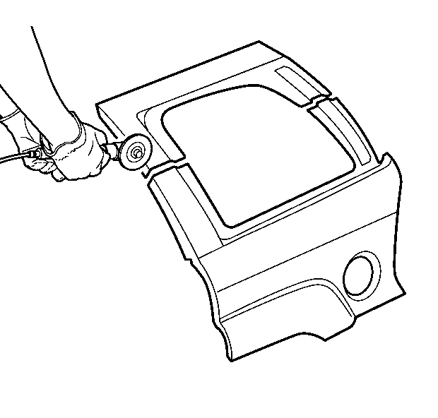
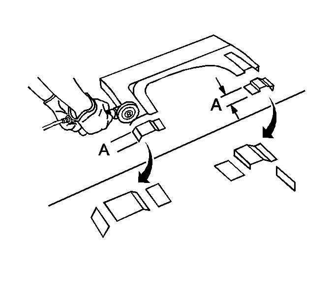
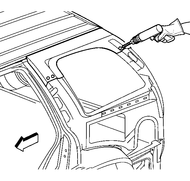
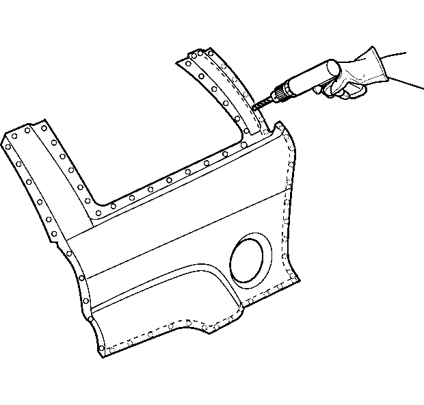
Note: If the location of the original plug weld holes cannot be determined, or if structural weld-thru adhesive was present, space the plug weld holes every 40 mm (1 1/2 in) apart.
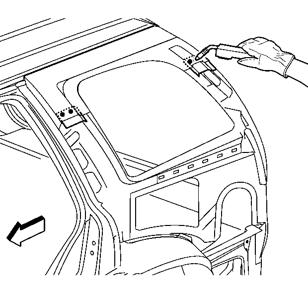
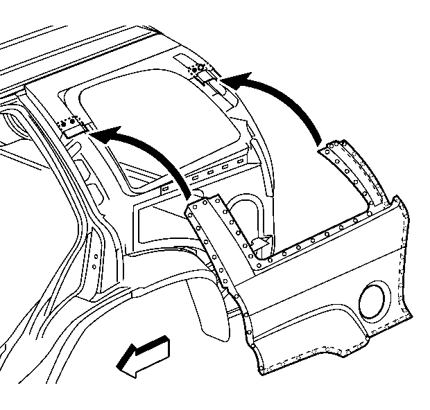
Warning: Properly seal the fuel filler opening before you position the quarter panel. Failure to seal the opening could allow exhaust gas to leak into the interior of the vehicle, causing personal injury.
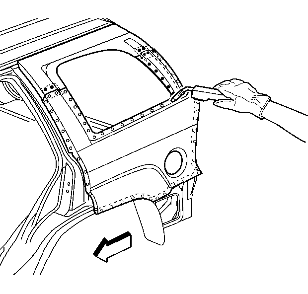
Note: To create a solid weld with minimum heat distortion, make 25 mm (1 in) stitch welds along the seam with 25 mm (1 in) gaps between them. Complete the stitch weld.
Quarter Outer Panel Sectioning Avalanche Weld-On
Removal Procedure
Warning: Refer to Approved Equipment for Collision Repair Warning in the Preface section.
Warning: Refer to Glass and Sheet Metal Handling Warning in the Preface section.
Warning: Refer to Collision Sectioning Warning in the Preface section.
- Disable the SIR system. Refer to SIR Disabling and Enabling.
- Disconnect the negative battery cable. Refer to Battery Negative Cable Disconnection and Connection.
- Remove all related panels and components.
- Repair as much of the damage as possible to factory specifications. Refer to Dimensions - Body.
- Note the location and remove the sealers and anti-corrosion materials from the repair area, as necessary. Refer to Anti-Corrosion Treatment and Repair.
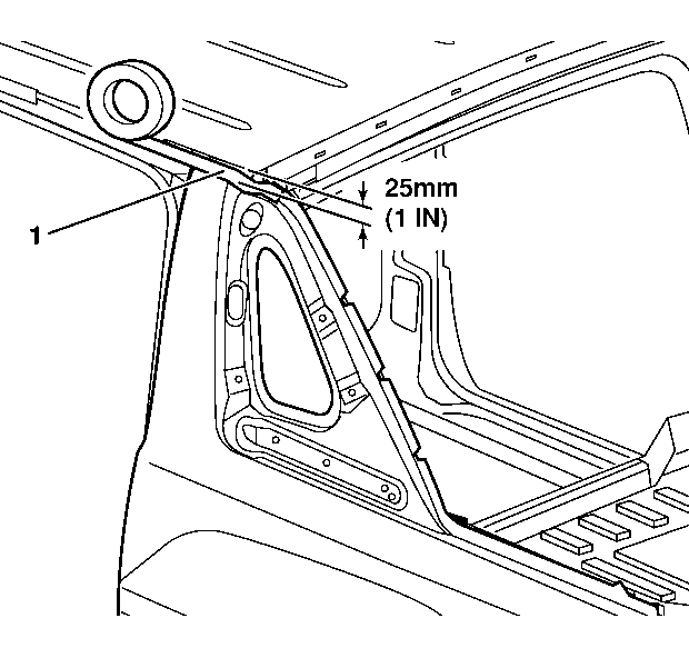
- Apply 25 mm (1 in) wide tape (1) along the upper edge of the quarter panel at the roof line.
- Cut the quarter panel at the bottom edge of the tape.
- Locate and drill out all factory welds. Note the number and location of welds for installation of the service part.
- Remove the damaged quarter panel, leaving a 25 mm (1 in) flange attached to the roof.
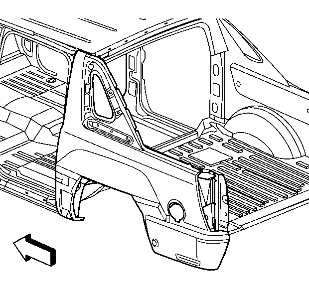
Note: The quarter panel can be serviced as a complete panel or sectioned. When the complete panel replacement is performed, the roof panel must be removed.
Warning: Refer to Foam Sound Deadeners Warning in the Preface section.
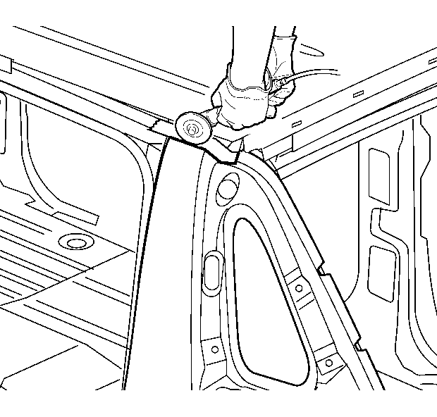
Note: Do not damage any inner panels or reinforcements.
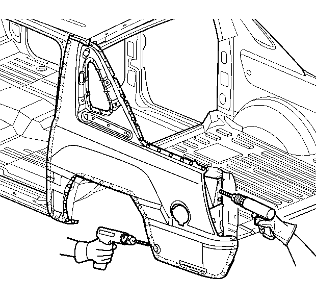
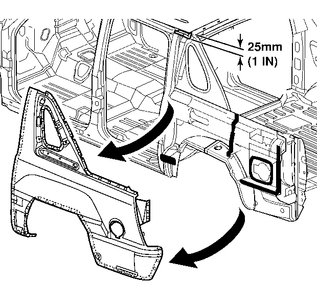
Installation Procedure
- Trim and discard the upper mounting flange on the service quarter panel so that it will fit over the 25 mm (1 in) flange left from the original panel.
- Drill 8 mm (5/16 in) plug weld holes (1) along the sectioning cut on the service part. Locate these holes 13 mm (1/2 in) from the edge and spaced 40 mm (1 1/2 in) apart.
- Drill 8 mm (5/16 in) plug weld holes in the service part as necessary in the locations noted from the original panel and along the sectioning cut.
- Prepare all attachment surfaces as necessary.
- Apply GM-approved Weld-Thru Coating or equivalent to all mating surfaces. Refer to Anti-Corrosion Treatment and Repair.
- Apply internal sealers (1) in the locations noted from the removal procedure.
- Position the quarter panel to the vehicle.
- Plug weld accordingly.
- To create a solid weld with minimum heat distortion, make 25 mm (1 in) stitch welds along the seam with 25 mm (1 in) gaps between them. Then go back and complete the stitch weld.
- Clean and prepare all welded surfaces.
- Clean and prepare all welded surfaces.
- Apply the sealers and anti-corrosion materials to the repair area, as necessary. Refer to Anti-Corrosion Treatment and Repair.
- Paint the repair area. Refer to Basecoat/Clearcoat Paint Systems.
- Install all related panels and components.
- Connect the negative battery cable. Refer to Battery Negative Cable Disconnection and Connection.
- Enable the SIR system. Refer to SIR Disabling and Enabling.
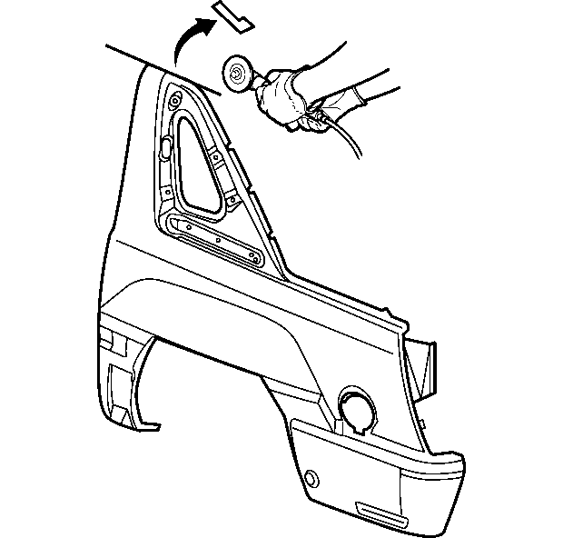
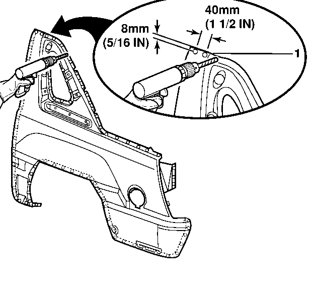
Note: In any area damaged beyond recognition, space plug weld holes every 40 mm (1 1/2 in) apart.
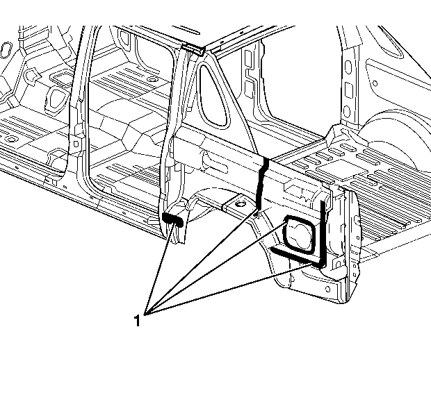
Warning: Properly seal the fuel filler opening before you position the quarter panel. Failure to seal the opening could allow exhaust gas to leak into the interior of the vehicle, causing personal injury.
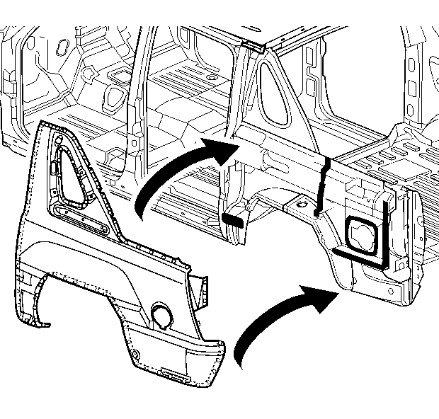
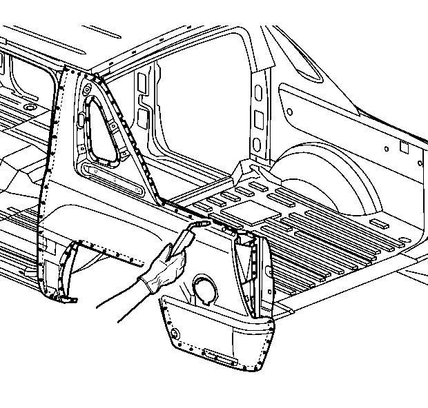
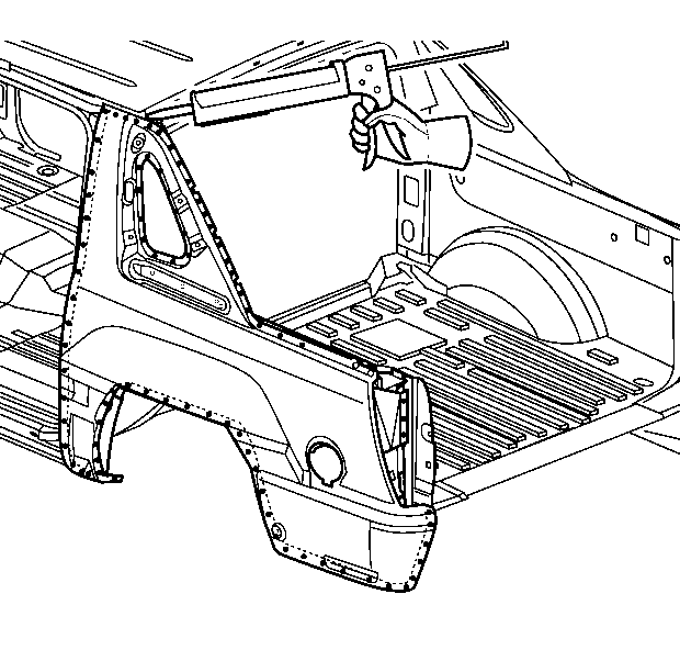
Note: Prior to refinishing, refer to publication GM 4901MD GM Approved Refinish Materials for recommended products. Do not combine paint systems. Refer to paint manufacturer's recommendations.
Quarter Outer Panel Sectioning Avalanche Bond-On
Removal Procedure
Warning: Refer to Approved Equipment for Collision Repair Warning in the Preface section.
Warning: Refer to Glass and Sheet Metal Handling Warning in the Preface section.
Warning: Refer to Collision Sectioning Warning in the Preface section.
- Disable the SIR system. Refer to SIR Disabling and Enabling.
- Disconnect the negative battery cable. Refer to Battery Negative Cable Disconnection and Connection.
- Remove all related panels and components.
- Repair as much of the damage as possible to factory specifications. Refer to Dimensions - Body.
- Note the location and remove the sealers and anti-corrosion materials from the repair area, as necessary. Refer to Anti-Corrosion Treatment and Repair.
- Apply 25 mm (1 in) wide tape (1) along the upper edge of the quarter panel at the roof line.
- Cut the quarter panel at the bottom edge of the tape.
- Locate and drill out all necessary factory welds.
- Remove the damaged quarter panel, leaving a 25 mm (1 in) flange attached to the roof.

Note: This adhesive bonding procedure represents one manufacturer's installation application. Other manufacturers' procedures may vary, including MIG welding in some areas of the repair. Always follow the system manufacturer's instructions for application, handling, and curing.
Note: Before you begin the repair, refer to Metal Panel Bonding and to Overlap/Backing Plate Sectioning.
Warning: Refer to Foam Sound Deadeners Warning in the Preface section.


Note: Do not damage any inner panels or reinforcements.


Installation Procedure
- Trim and discard the upper weld flange on the service quarter panel so that the service panel will fit over the 25 mm (1 in) flange left over from the original panel.
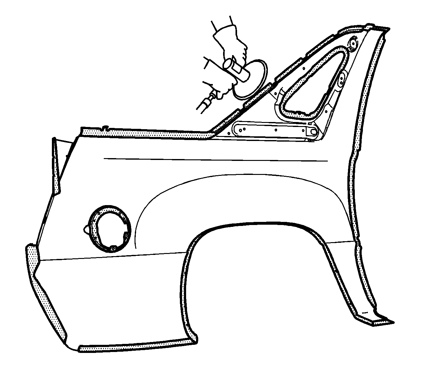
- Grind the surface of the body mating flanges to bare steel. Do not damage the corners or thin the metal during the grinding process.
- Grind the quarter panel mating flanges to remove the E-coating. Take care not to damage the corners or thin the metal during the grinding operation.
- Ensure proper alignment of the replacement panel.
- Clean the mating surfaces.
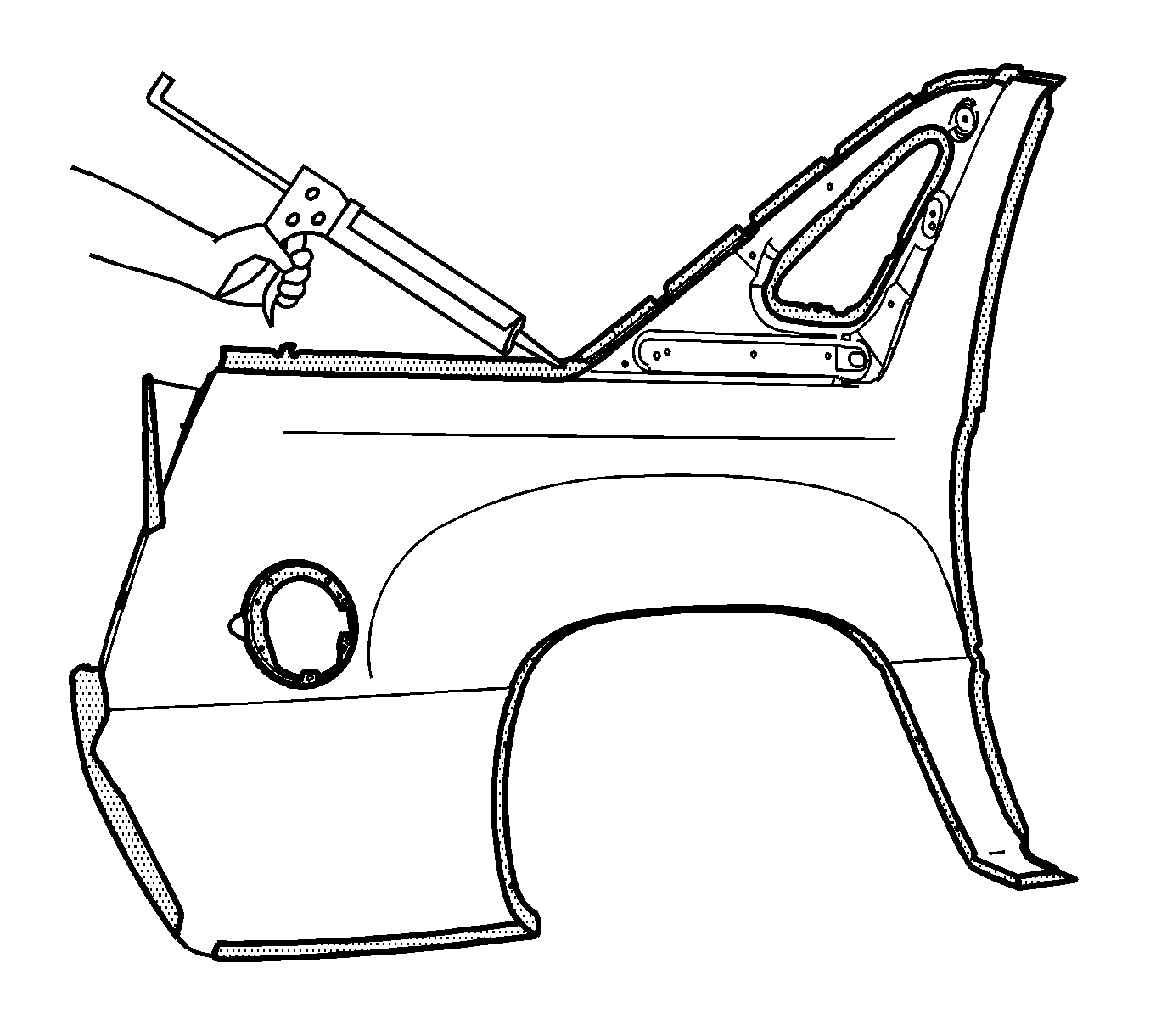
- Apply a 3-6 mm (1/8 to 1/4 in) bead of metal panel bonding adhesive to both of the mating surfaces.
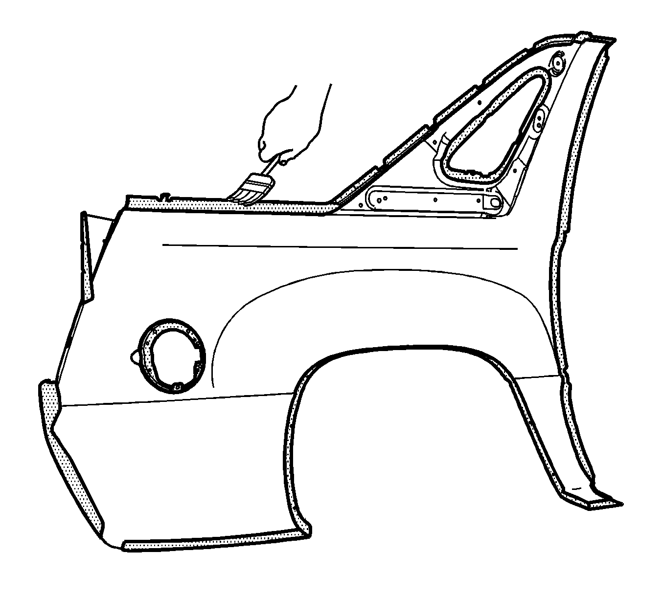
- Using a small acid brush, spread a coat of adhesive to both of the mating surfaces. Cover all of the bare metal to ensure corrosion protection.
- Apply a 9-13 mm (3/8 to 1/2 in) bead of metal panel bonding adhesive to the mating surface of the service quarter panel.
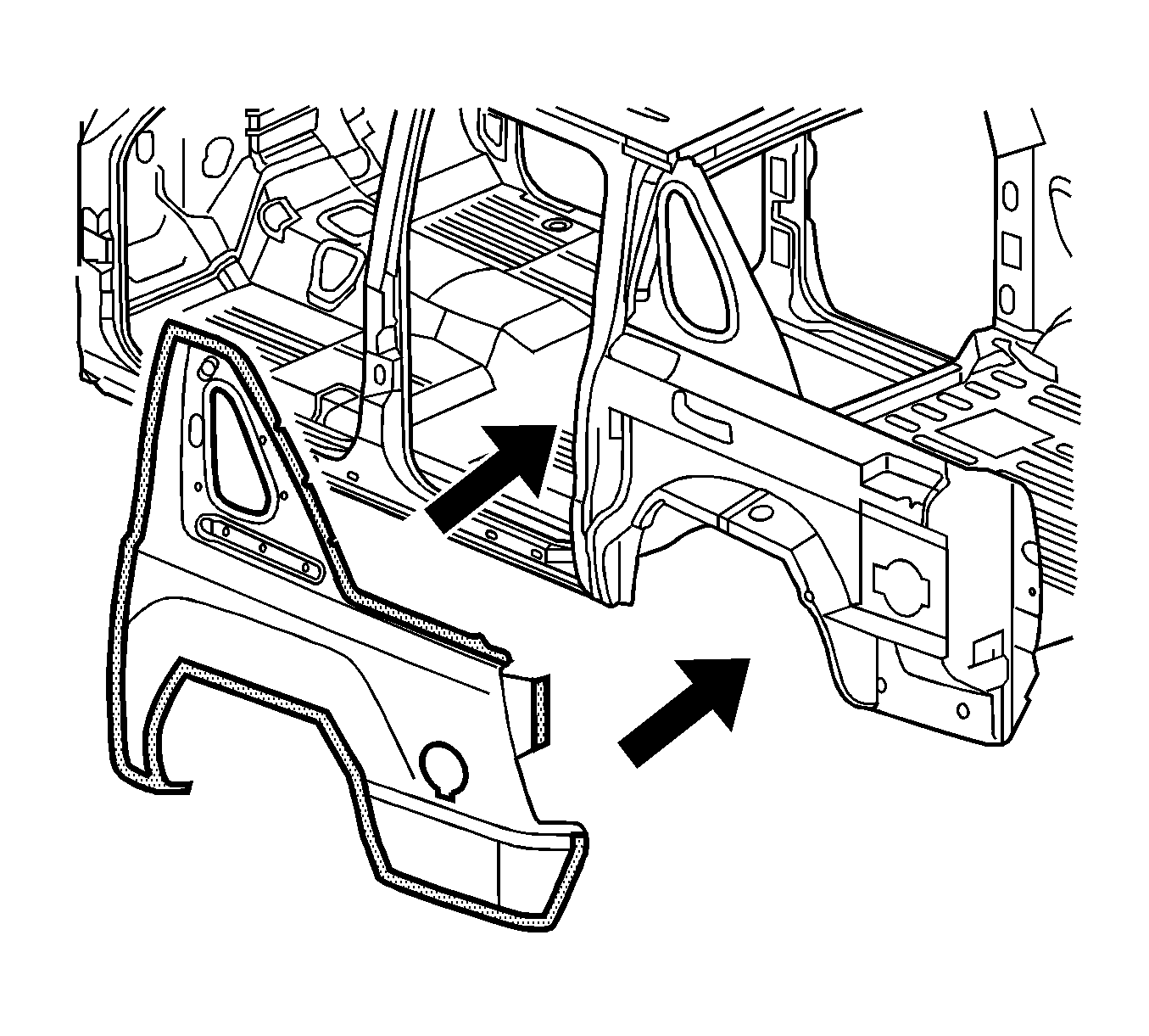
- Position the quarter panel to the body.
- Clamp the quarter panel into position.
- Using lacquer thinner remove the excess adhesive from the quarter panel area.
- Apply body filler as necessary , according to the adhesive manufacturer's recommendations.
- Apply the sealers and anti-corrosion materials to the repair area, as necessary. Refer to Anti-Corrosion Treatment and Repair.
- Paint the repair area. Refer to Basecoat/Clearcoat Paint Systems.
- Install all related panels and components.
- Connect the negative battery cable. Refer to Battery Negative Cable Disconnection and Connection.
- Enable the SIR system. Refer to SIR Disabling and Enabling.

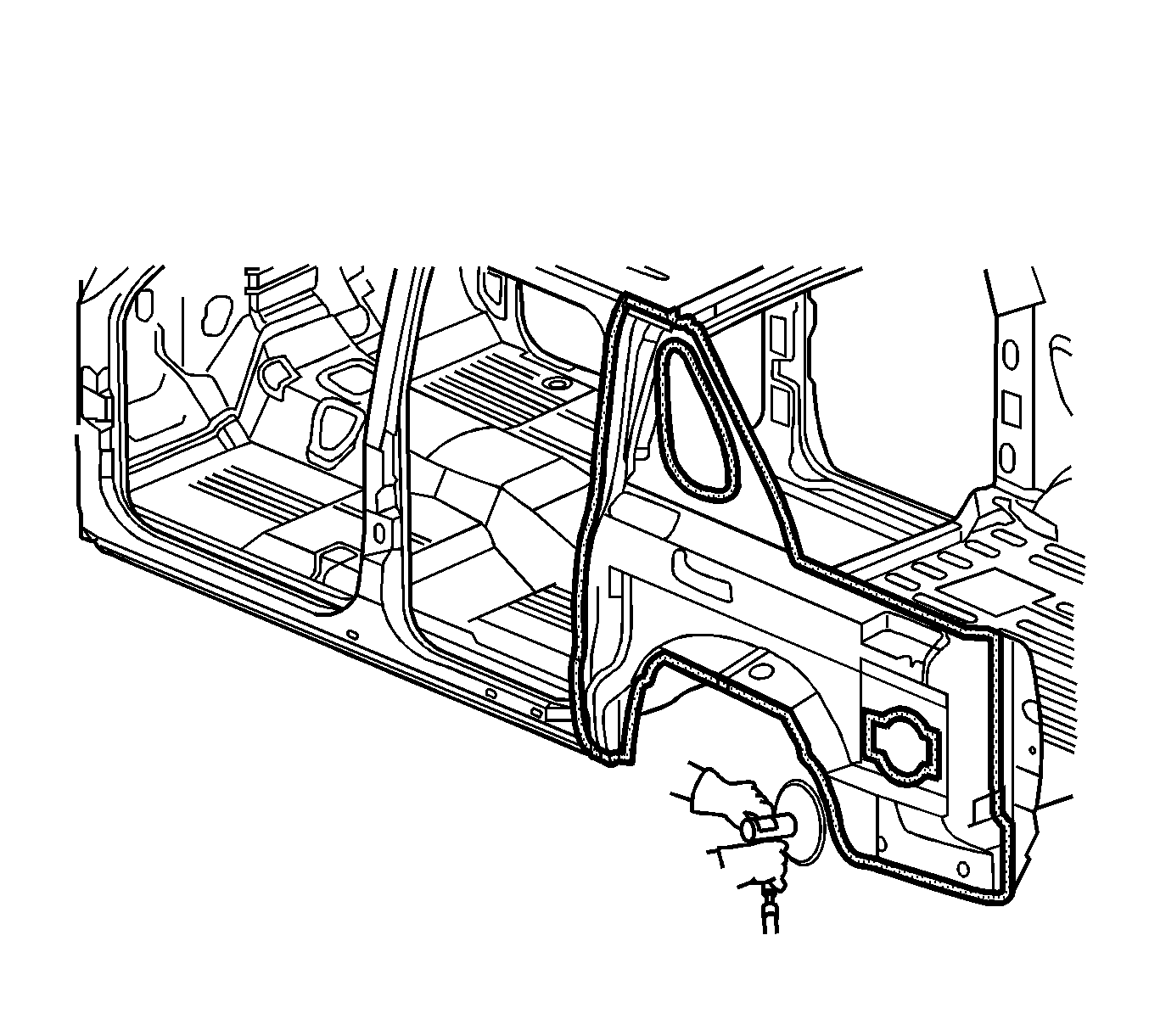
Warning: Properly seal the fuel filler opening before you position the quarter panel. Failure to seal the opening could allow exhaust gas to leak into the interior of the vehicle, causing personal injury.
Note: The adhesive has a 40-50 minute working time. Do not allow the adhesive to cure prior to installing the quarter panel.
Note: DO NOT pull the panels apart after joined together. Slide the panels against each other to realign the panels.
