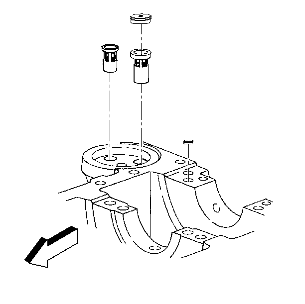
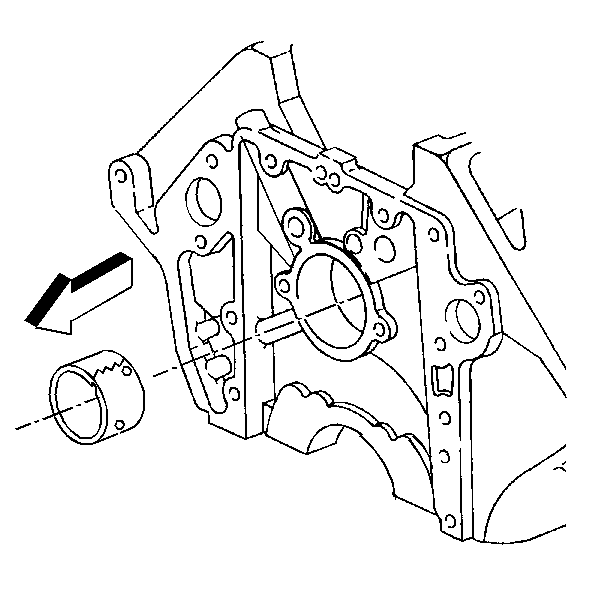
- Install the oil cooler bypass valve using a socket the same size as the outside
diameter of the valve. Drive the valve into the bore until the valve seats
on the shoulder in the bore.
Important: The cup plug has an orifice hole that prevents an air lock from occurring
and blocking the oil flow.
- Install the cup plug for the oil cooler bypass valve.
- Install the oil filter bypass valve using a socket the same size
as the outside diameter of the valve. Drive the valve into the bore until
the valve seats on the shoulder in the bore.
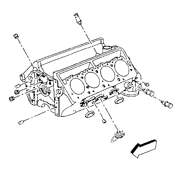
- Install the front camshaft oil gallery plugs.
| • | Do not use sealer. The pre-applied sealer is reusable. |
| • | Tighten the plugs until they are completely seated. |
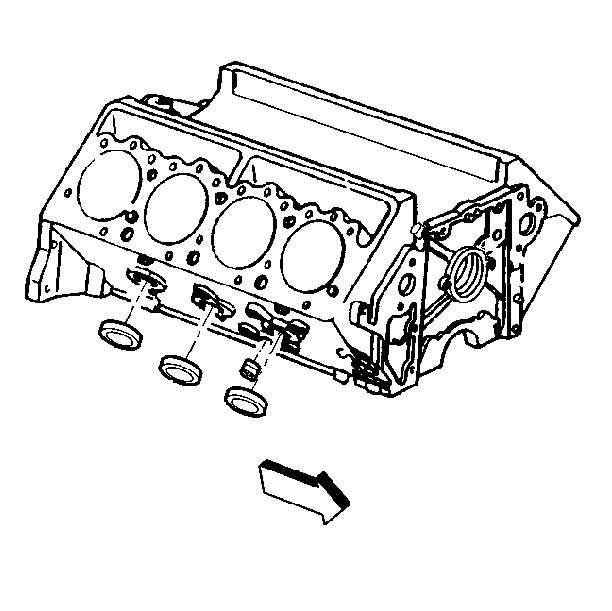
- Install the side oil gallery plugs.
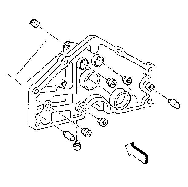
- Install the remaining oil gallery plugs. An oil gallery plug is located inside
the rear main bearing cap land. On threaded plugs, use GM P/N 12346004 or
the equivalent.
Tighten
Tighten oil gallery plugs to 34 N·m (25 lb ft).
Notice: Use the correct fastener in the correct location. Replacement fasteners
must be the correct part number for that application. Fasteners requiring
replacement or fasteners requiring the use of thread locking compound or sealant
are identified in the service procedure. Do not use paints, lubricants, or
corrosion inhibitors on fasteners or fastener joint surfaces unless specified.
These coatings affect fastener torque and joint clamping force and may damage
the fastener. Use the correct tightening sequence and specifications when
installing fasteners in order to avoid damage to parts and systems.
- Install the engine oil pressure sensor switch.
- Install the cup plugs and the block heater. Use GM P/N 12345382
or the equivalent on the cup plugs.
- Install the coolant drain plugs.
Tighten
Tighten the coolant drain plugs to 25 N·m (18 lb ft).
Important:
| • | All bearing locations are viewed from the front of the block,
with the block in an upright position. The camshaft bearing bores vary in
size. On the back of the camshaft bearing is the bore location number from
one through five. Be sure to fit the correct camshaft bearing into the correct
bore. |
| • | The outer camshaft bearings must be installed first. These bearings
serve as guides for the tool. |
| • | The rear camshaft bearing must be installed from the front of
the block and the front camshaft bearing must be installed from the rear of
the block. This allows the tool to remain centered. |
| • | There is one oil hole in the rear camshaft bearing. Using the
seam in the 11 o'clock position as a reference point, the oil hole must be
in the 1 o'clock position. Be sure that the oil hole in the camshaft bearing
lines up with the oil hole in the block. |
- Install the rear camshaft bearing using the J 33049
.
| 10.1. | Insert the driving bar with the correct expanding driver into
the camshaft bearing (collet 4 for camshaft bearing one). |
| 10.2. | Turn the tool until the collet has tightened in the bearing. |
| 10.3. | Push the guide cone against the block and into the fifth bearing
bore to center the tool. |
| 10.4. | Drive the bearing into the block. |
Important: There are two oil holes in the front camshaft bearing. Using the seam
in the 12 o'clock position, and the notch facing the front of the block as
reference points, one oil hole will be in the 1 o'clock position and the other
oil hole will be in the 4:30 position. Be sure that both oil holes in the
camshaft bearing line up with the oil holes in the block.
- Install the front camshaft bearing using the J 33049
.
| 11.1. | Insert the driving bar with the correct expanding driver into
the camshaft bearing (collet 3 for camshaft bearing five). |
| 11.2. | Turn the tool until the collet has tightened in the bearing. |
| 11.3. | Push the guide cone against the block and into the first bearing
bore to center the tool. |
| 11.4. | Drive the bearing into the block. |
Important: There is one oil hole in the center camshaft bearings. Using the seam
in the 11 o'clock position as a reference point, the oil hole must be in the
1 o'clock position. Be sure that the oil hole in the camshaft bearing lines
up with the oil hole in the block.
- Install the inner camshaft bearings using the J 33049
.
| 12.1. | Insert the driving bar with the correct expanding driver into
the camshaft bearing (collet 4 for camshaft bearings two through four). |
| 12.2. | Turn the tool until the collet has tightened in the bearing. |
| 12.3. | Push the guide cone against the block and into the first bearing
bore to center the tool. |
| 12.4. | Drive the bearing into the block. |
| 12.5. | Repeat this procedure in order to install the remaining camshaft
bearings. |
- Install a new rear camshaft plug.
| 13.1. | Use sealer GM P/N 12345382 or equivalent on the camshaft plug. |
| 13.2. | Install the plug flush or to a maximum of 0.80 mm (0.03 in)
deep. |


