Removal Procedure
- Remove the intake manifold. Refer to Intake Manifold Replacement .
- Remove the fuel injection lines and clips. Refer to Engine Controls.
- Remove the CDR valve and hose (right side).
- Remove the long pencil brace to the turbocharger (right side).
- Remove the ground strap.
- Remove the heater hose (right side).
- Remove the oil level indicator tube and bracket (left side).
- Remove the fuel return line clip at the valve rocker arm cover stud.
- Remove the wiring harness at the rear of the valve rocker arm cover from the clips and move aside.
- Remove the turbocharger heat shield (right side).
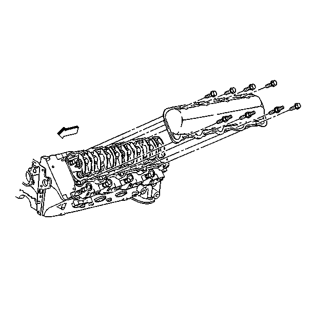
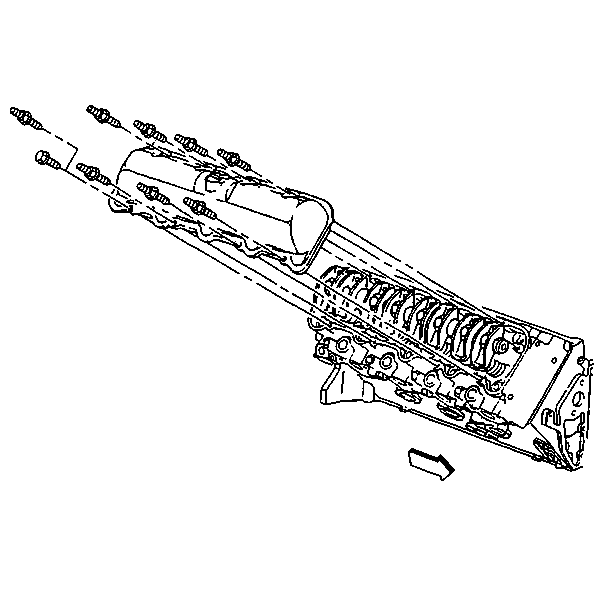
- Remove the valve rocker arm cover.
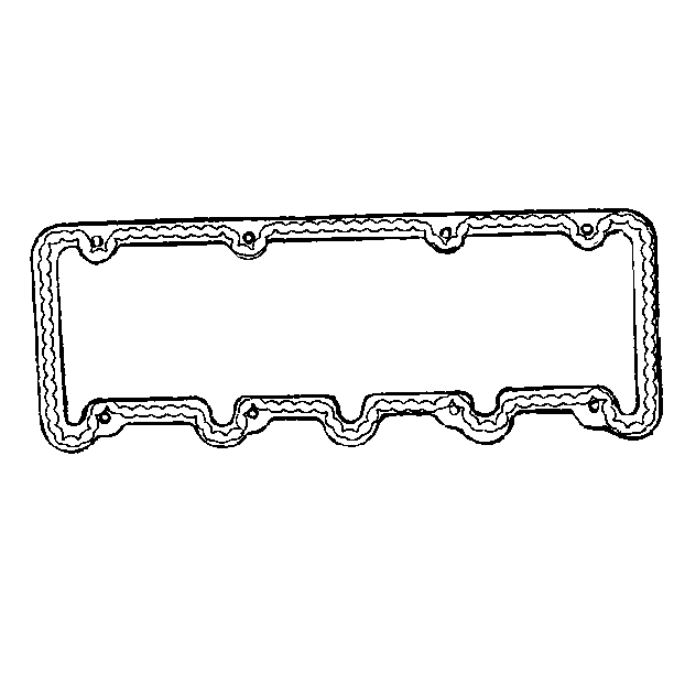
- Clean the RTV from the valve rocker arm cover and cylinder head. All loose RTV or pieces that will cause installation interference must be removed.
- Clean the oil and grease from the sealing surfaces on the valve rocker arm cover and cylinder head. Use a suitable solvent.
- Inspect the valve rocker arm cover sealing flanges for distortion. Replace as necessary.
Important: Do not bend the fuel injector lines in order to ease the removal of the valve rocker arm cover. Damage to the fuel injector lines will occur.
Important: Mark the fuel line clips and brackets in order to insure proper installation.
Important: Mark the fuel line clips and brackets in order to insure proper installation.
Important: Do not pry on the rocker arm cover. Prying on the rocker arm cover may cause damage to the sealing surfaces.


Installation Procedure
- Apply a 5 mm (3/16 in) bead of RTV sealant GM P/N 12345739 to the valve rocker arm covers, inboard of the bolt holes. The sealer must be wet to the touch when the bolts are tightened.
- Install the valve rocker arm cover.
- Install the wiring harness.
- Install the turbocharger heat shield (right side).
- Install the fuel return lines.
- Install the oil level indicator tube and the bracket (left side).
- Install the heater hose (right side).
- Install the ground strap.
- Install the long pencil brace to the turbocharger (right side).
- Install the CDR valve and hose (right side).
- Install the fuel injection lines and clips to their original location as marked during removal.
- Install the intake manifold. Refer to Intake Manifold Replacement .

Notice: Do not allow the RTV sealant to enter any blind threaded hole. RTV sealant that is allowed to enter a blind threaded hole can cause hydraulic lock of the fastener when the fastener is tightened. Hydraulic lock of a fastener can lead to damage to the fastener and/or the components. Hydraulic lock of a fastener can also prevent the proper clamping loads to be obtained when the fastener is tightened. Improper clamping loads can prevent proper sealing of the components allowing leakage to occur. Preventing proper fastener tightening can allow the components to loosen or separate leading to extensive engine damage.

Tighten
Tighten the bolts to 22 N·m (16 lb ft).
Notice: Use the correct fastener in the correct location. Replacement fasteners must be the correct part number for that application. Fasteners requiring replacement or fasteners requiring the use of thread locking compound or sealant are identified in the service procedure. Do not use paints, lubricants, or corrosion inhibitors on fasteners or fastener joint surfaces unless specified. These coatings affect fastener torque and joint clamping force and may damage the fastener. Use the correct tightening sequence and specifications when installing fasteners in order to avoid damage to parts and systems.

