Tools Required
| • | J 46003 Output Shaft Bearing Locknut Wrench |
| • | J 46001 Differential Drive Pinion Holding Tool |
Assembly
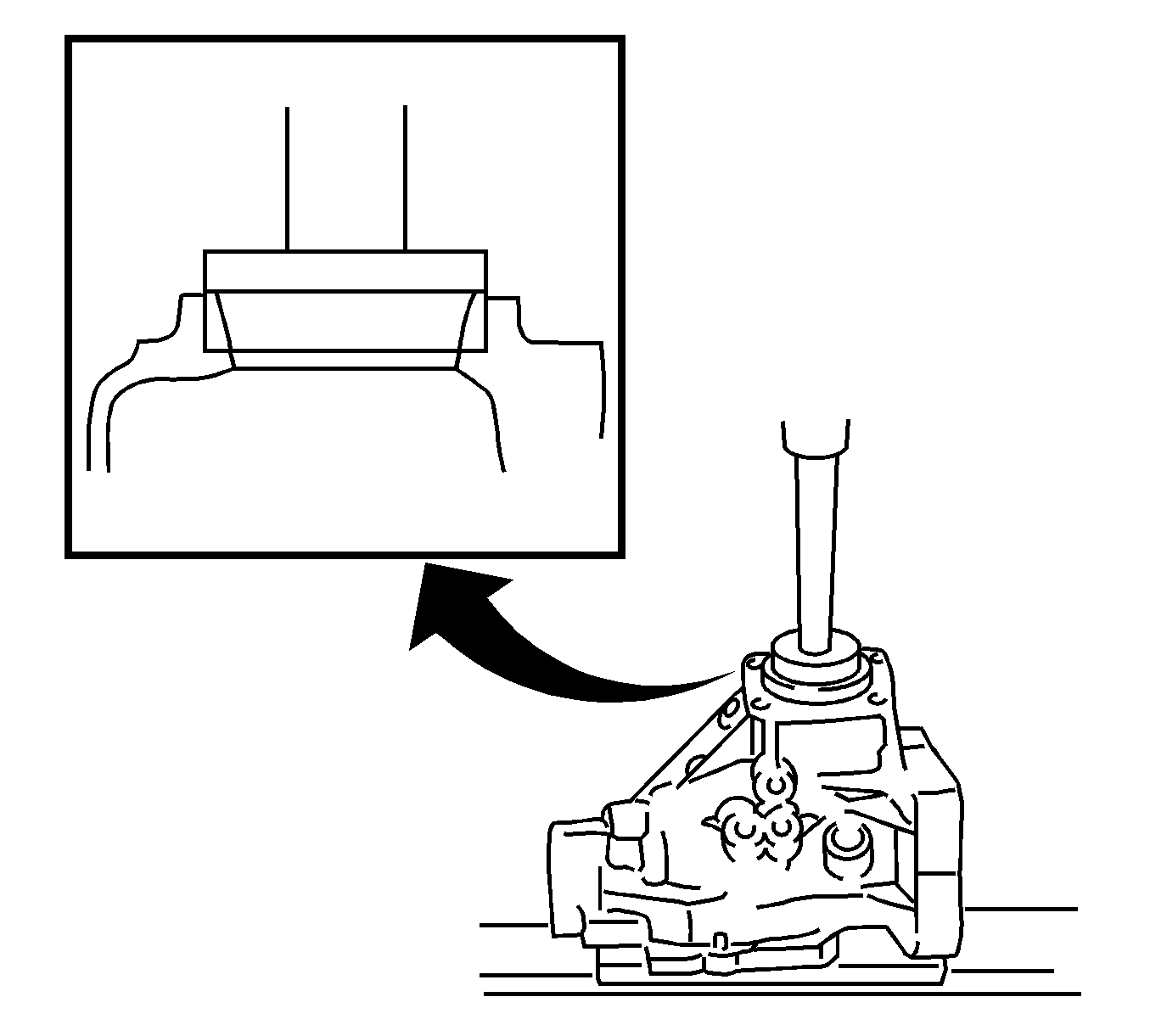
- Using a press, install the inner output shaft bearing race in the transfer case.
- Using a press, install the outer output shaft bearing race in the transfer case.
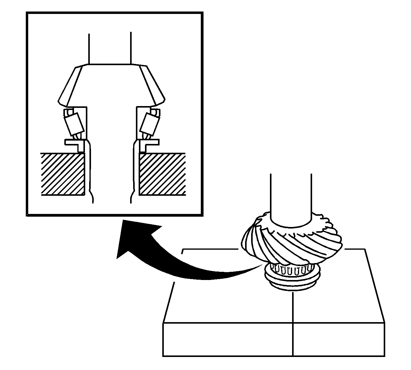
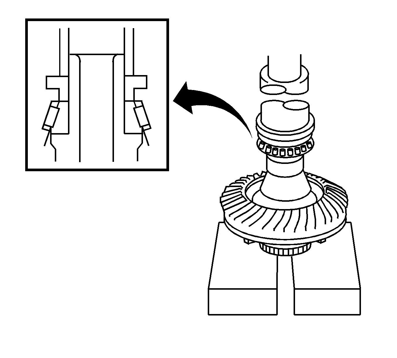
- Using a press, install the output shaft bearing on the output shaft.
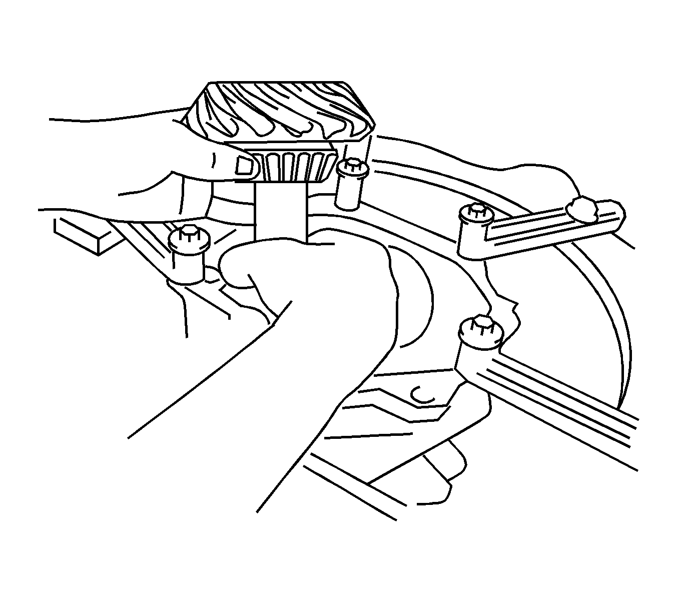
- Install the output shaft in the transfer case.
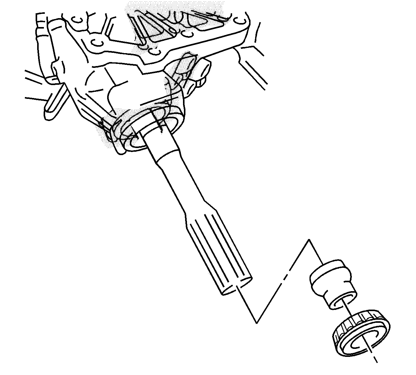
- Install the output shaft spacer on the output shaft.
- Install the outer output shaft bearing.
- Using J 46003 and J 46001 , install a new output shaft lock nut.
- Using J 46003 and a torque wrench, measure the output shaft preload.
- Clean the contact surface of the ring gear and the ring gear mounting case.
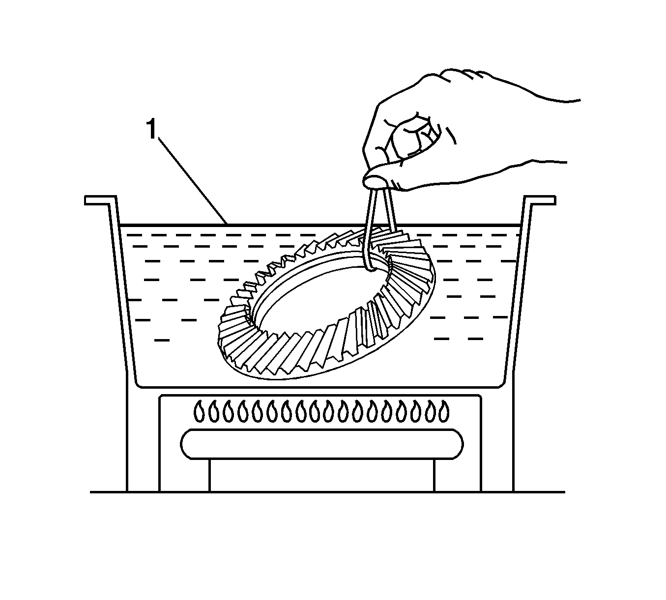
- Heat the ring gear in boiling water (1) for 10 minutes.
- Carefully remove the ring gear from the boiling water.
- After the moisture on the ring gear has completely evaporated, quickly install the ring gear to the mounting case.
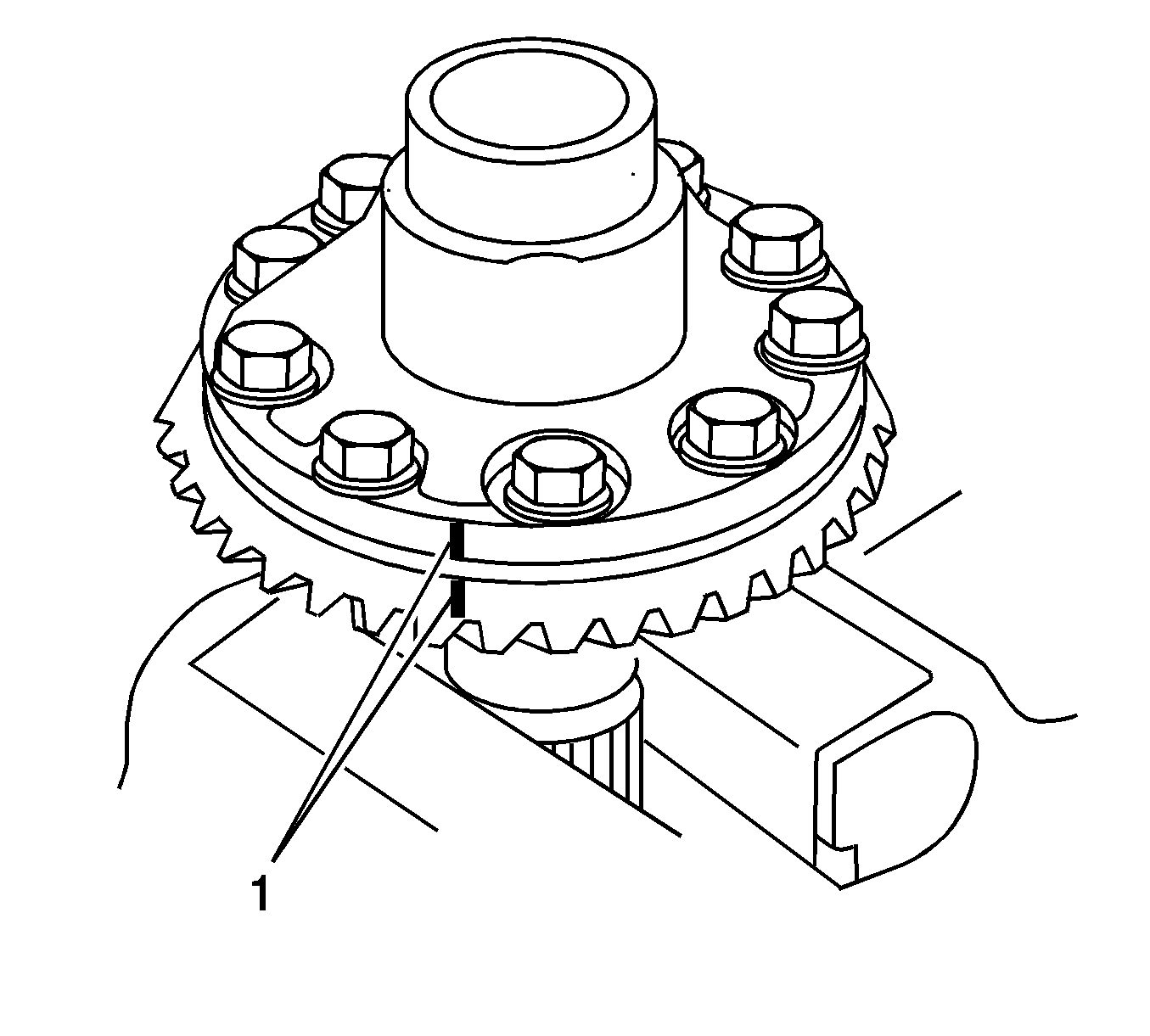
- Align the marks on the ring gear and mounting case.
- Allow the ring gear to cool before tightening the bolts.
- Install the 10 bolts.
- Tighten the bolts in a diagonal pattern.
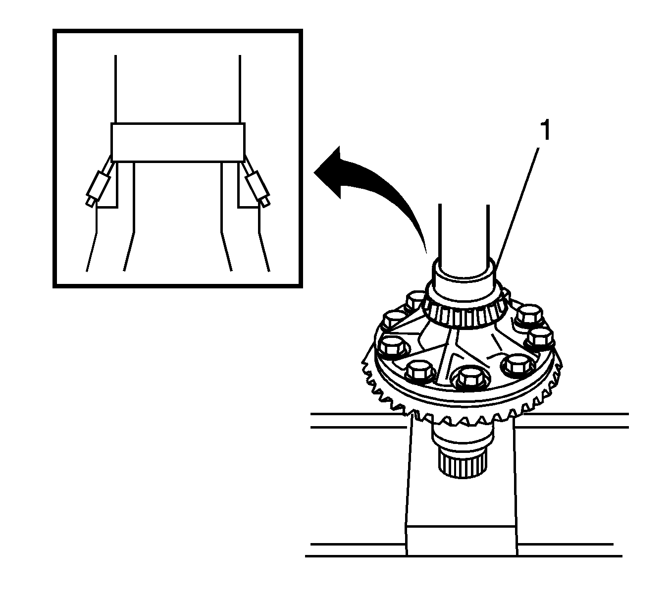
- Using a press, install the right bearing (1) on the mounting case.
- Using a press, install the left bearing on the mounting case.
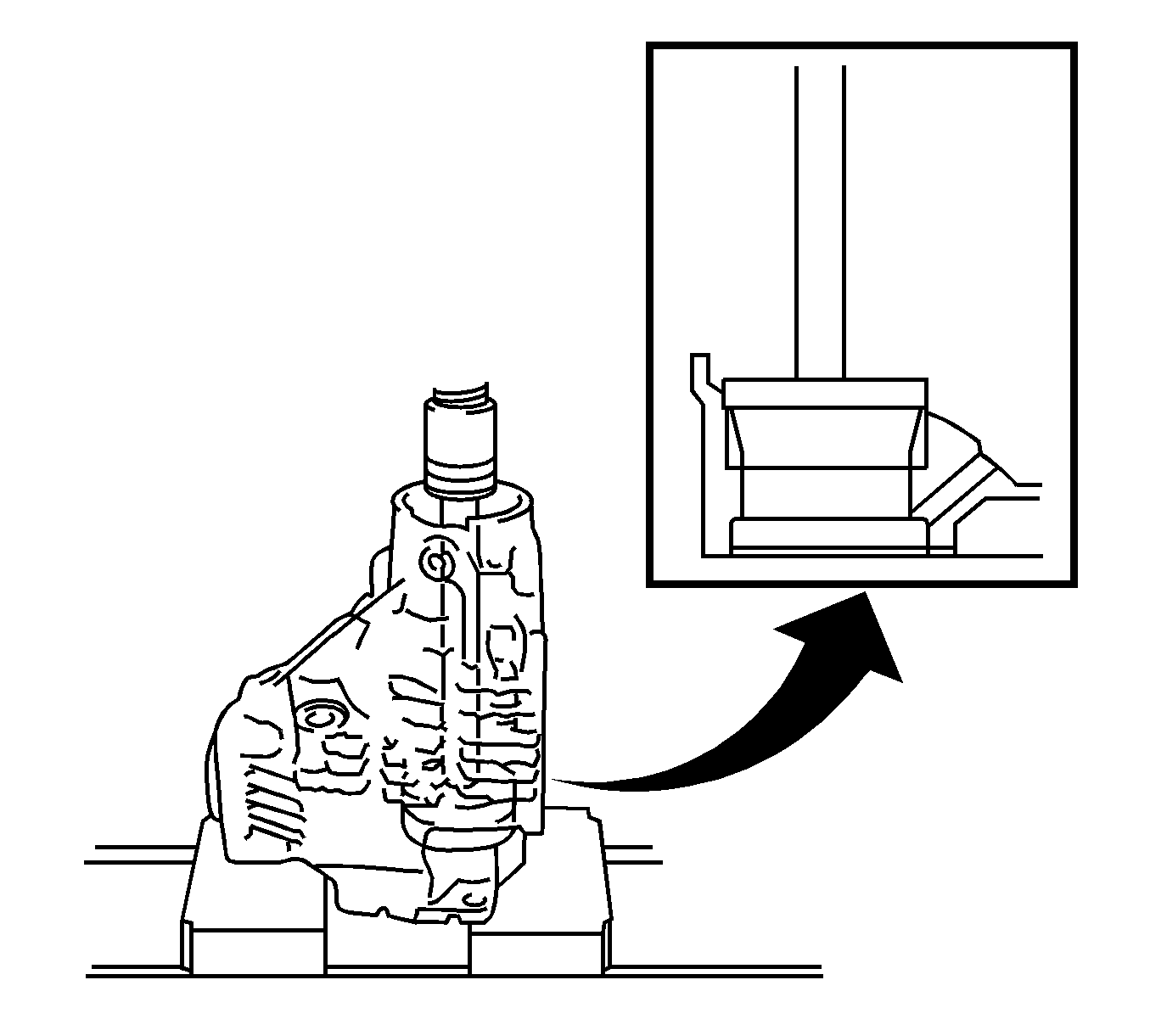
- Using a press, install the left mounting case outer bearing race in the transfer case.
- Apply gear oil the ring gear mounting case bearings.
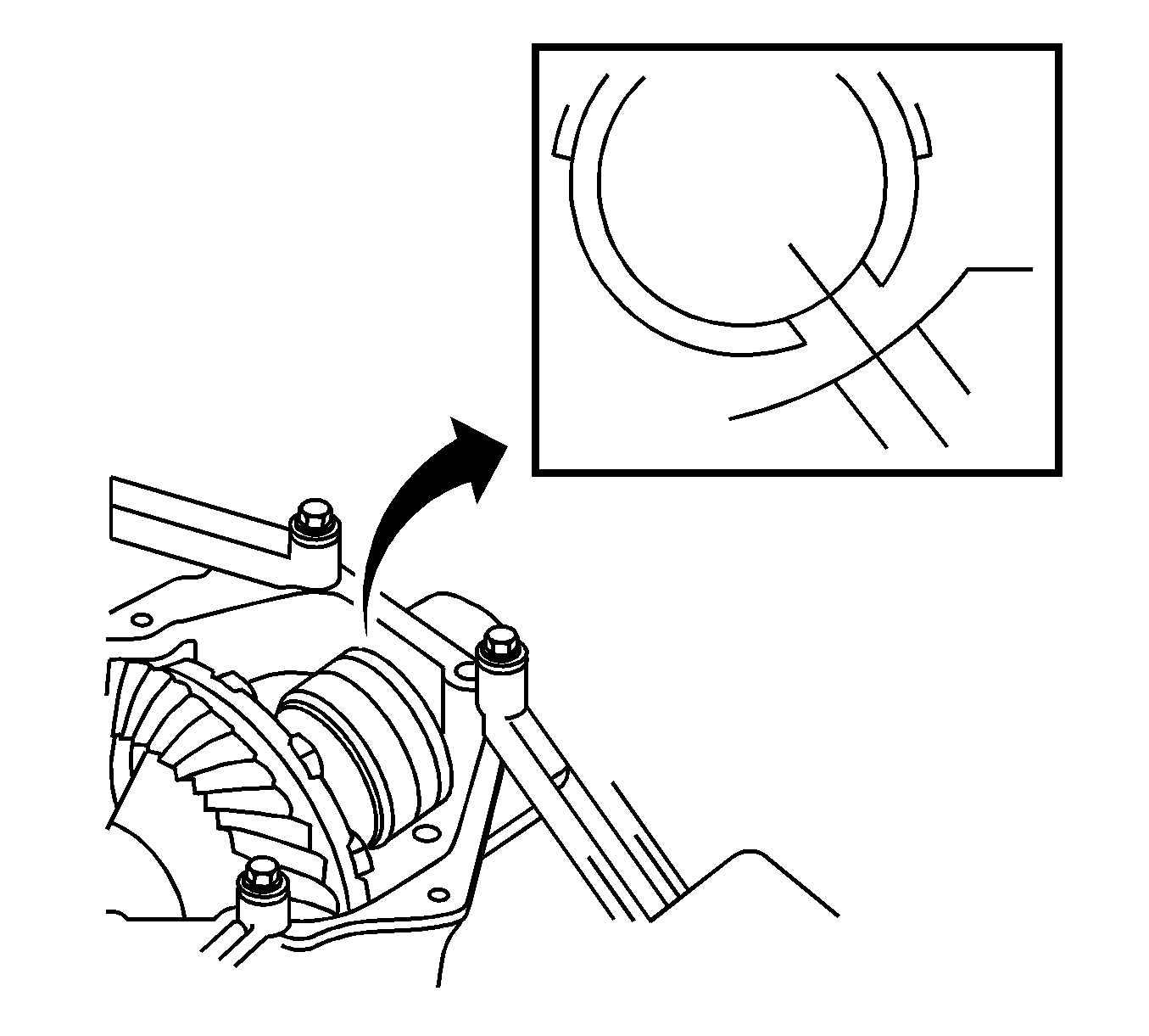
- Install the ring gear mounting case in the transfer case.
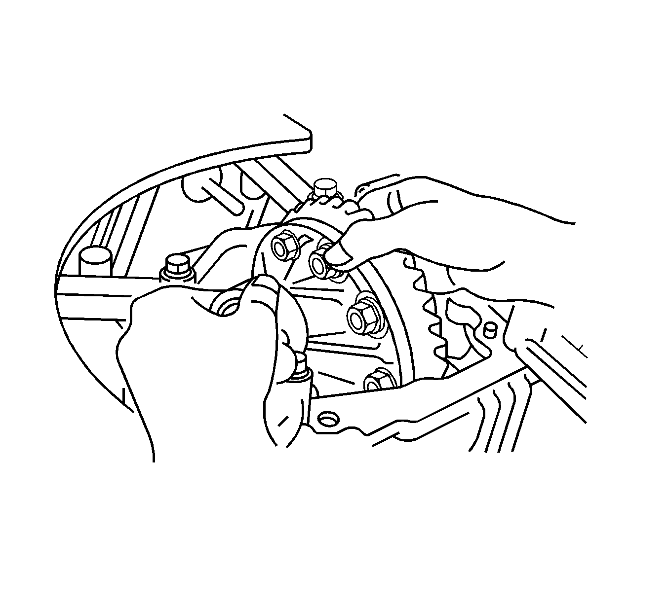
- Align the spacer with hole in the case.
- Install the spacer.
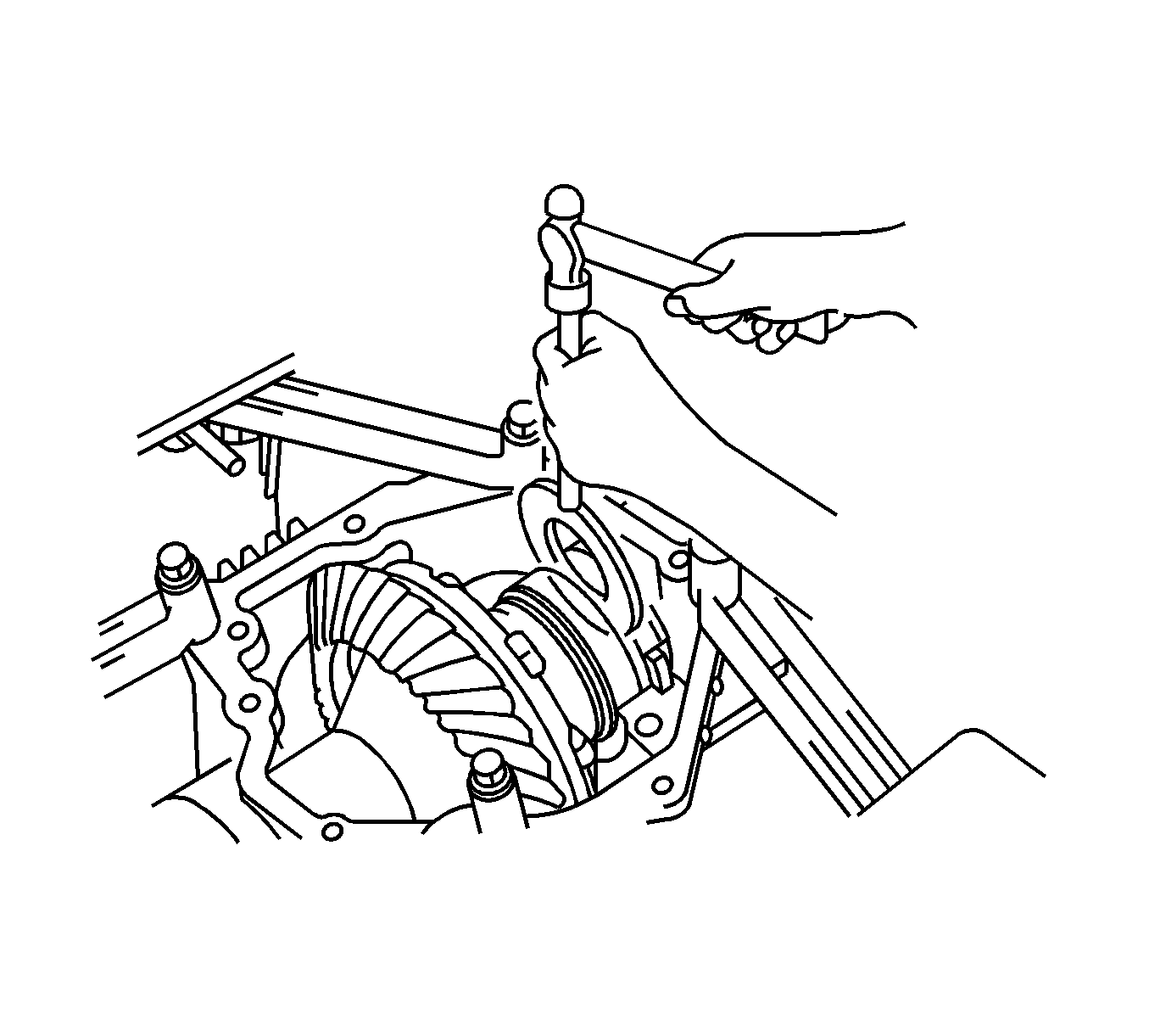
- Using a brass bar and hammer, install the ring gear mounting case washer.
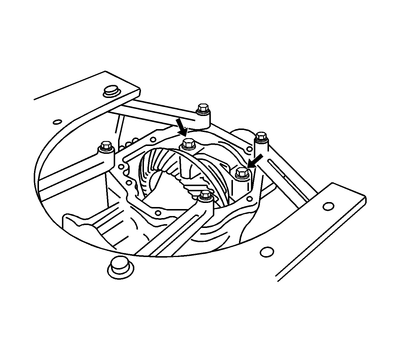
- Install the bearing cap and bolts.
- Tighten the bolts
- Using a dial indicator, check the backlash of the ring gear.
- If the backlash is not within the specified value, replace the ring gear mounting case left bearing side washer. For ring gear backlash shim selection, refer to General Specifications .
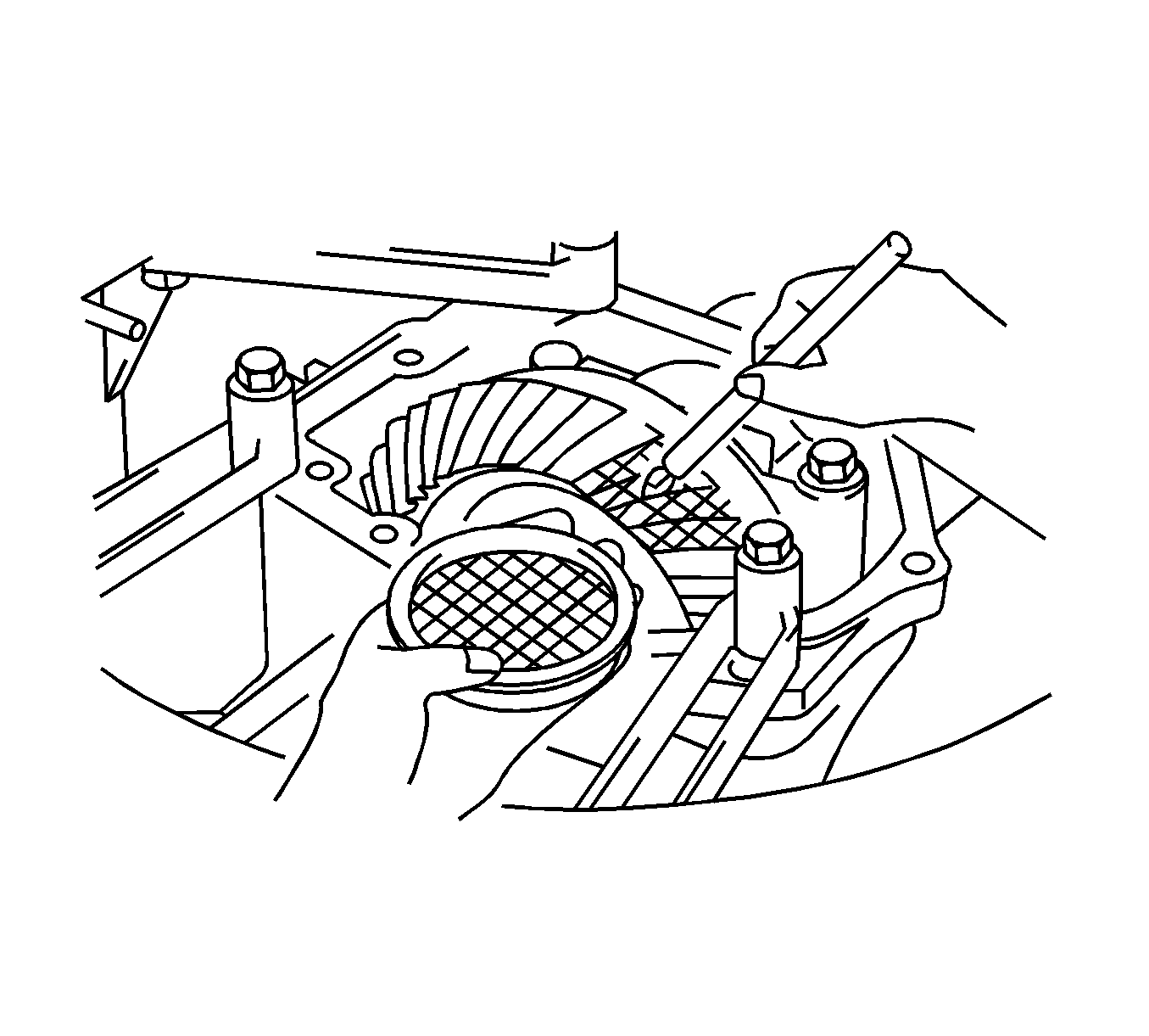
- Coat the teeth of the ring gear with Gear Marking Compound GM P/N 1052351 (Canadian P/N 10953497).
- Rotate the ring gear.
- Inspect the ring gear contact pattern. Refer to Gear Tooth Contact Pattern Inspection .
- If the gear tooth contact pattern is incorrect, replace the output shaft shim. Refer to Output Shaft Shim Selection Chart in General Specifications
- Using J 46003 (1) and a torque wrench, measure the output shaft preload.
- If output shaft total preload in not within specification, replace the shim. Refer to Preload Shim Selection Chart in General Specifications
- Using J 46003 and J 46001 , tighten the output shaft lock nut.
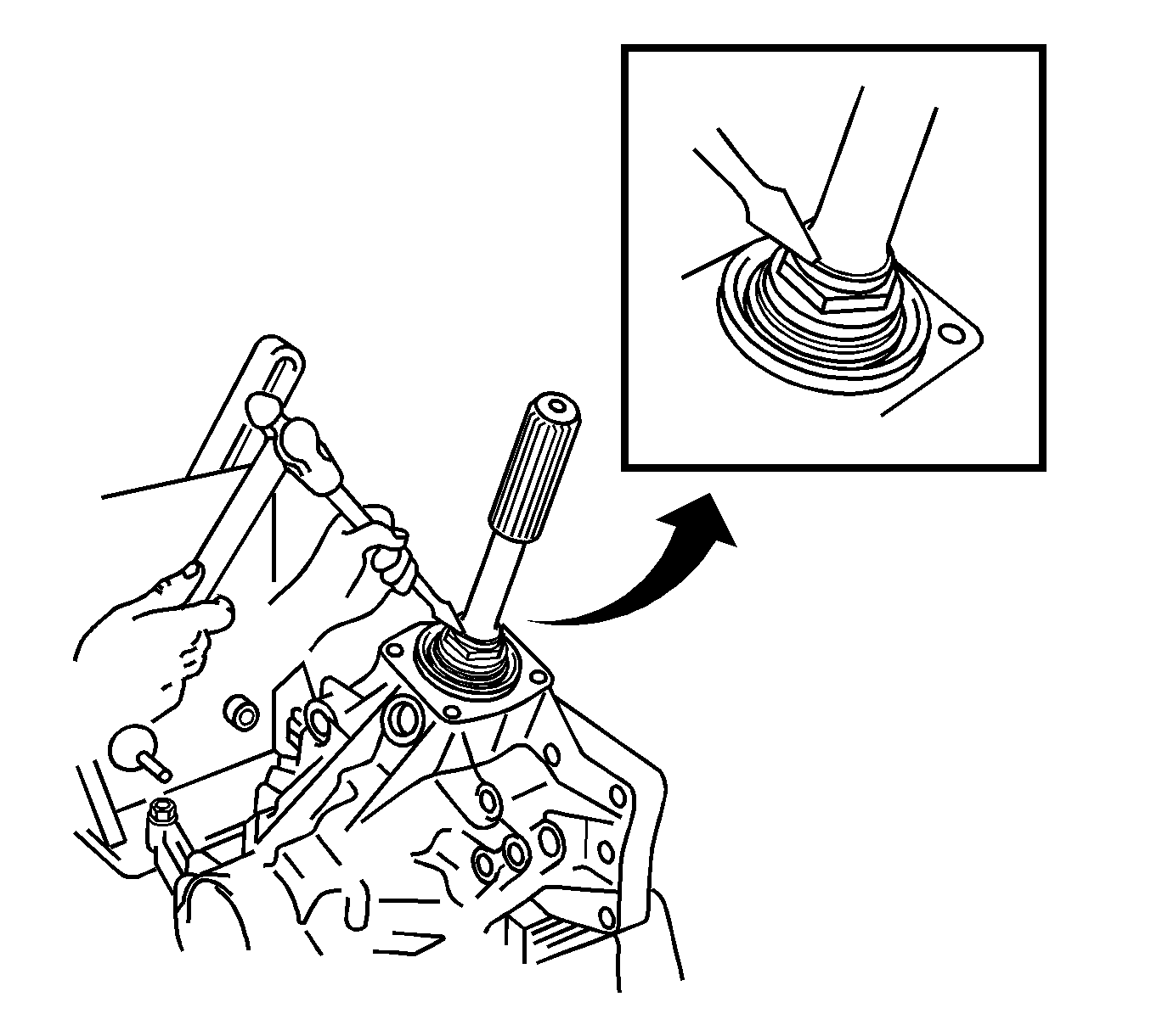
- Using a chisel and a hammer, stake the output shaft retaining nut.
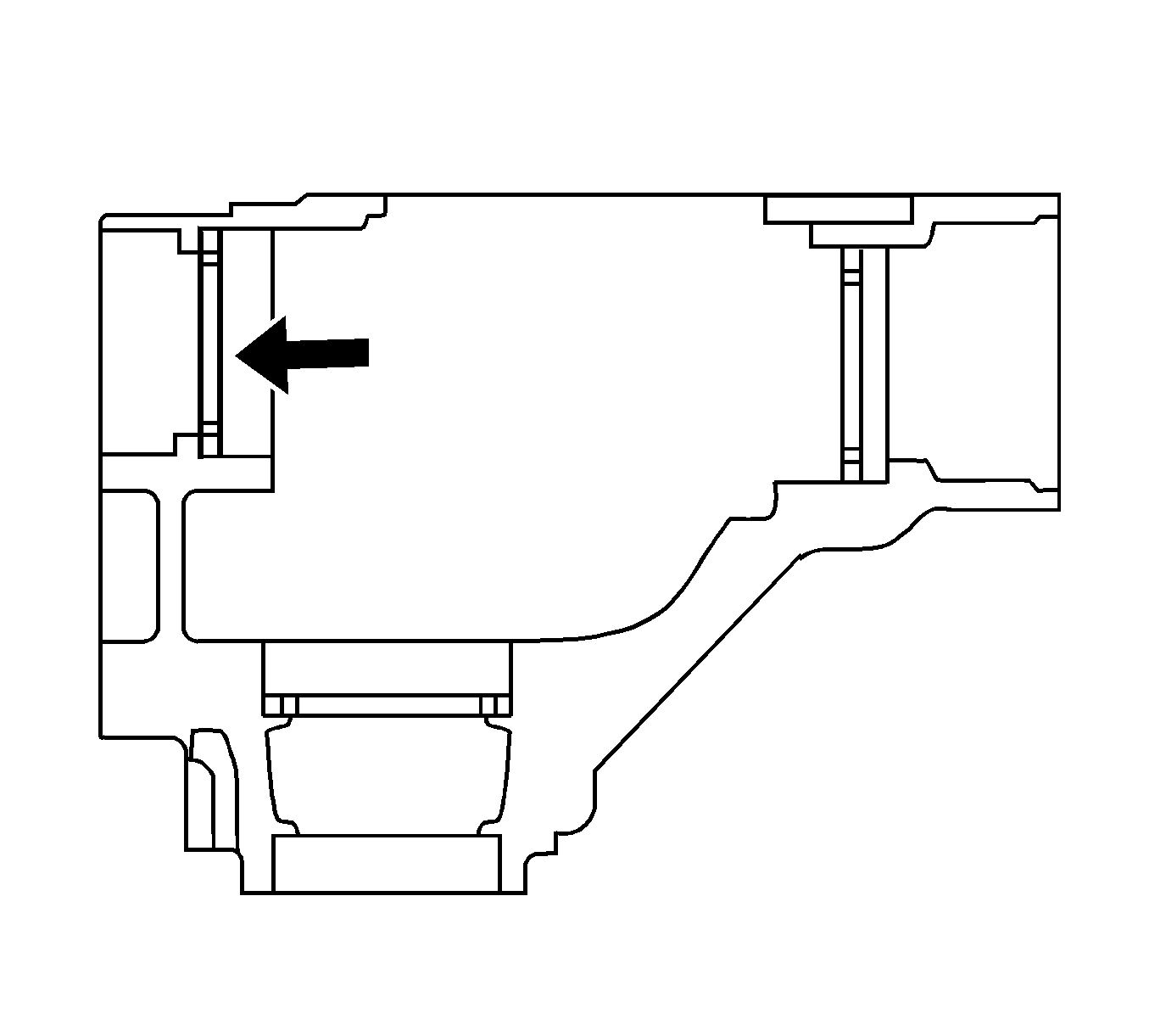
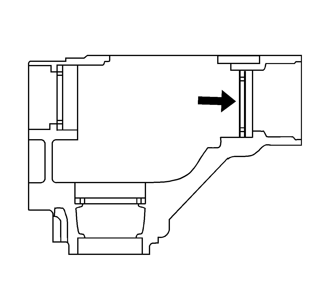
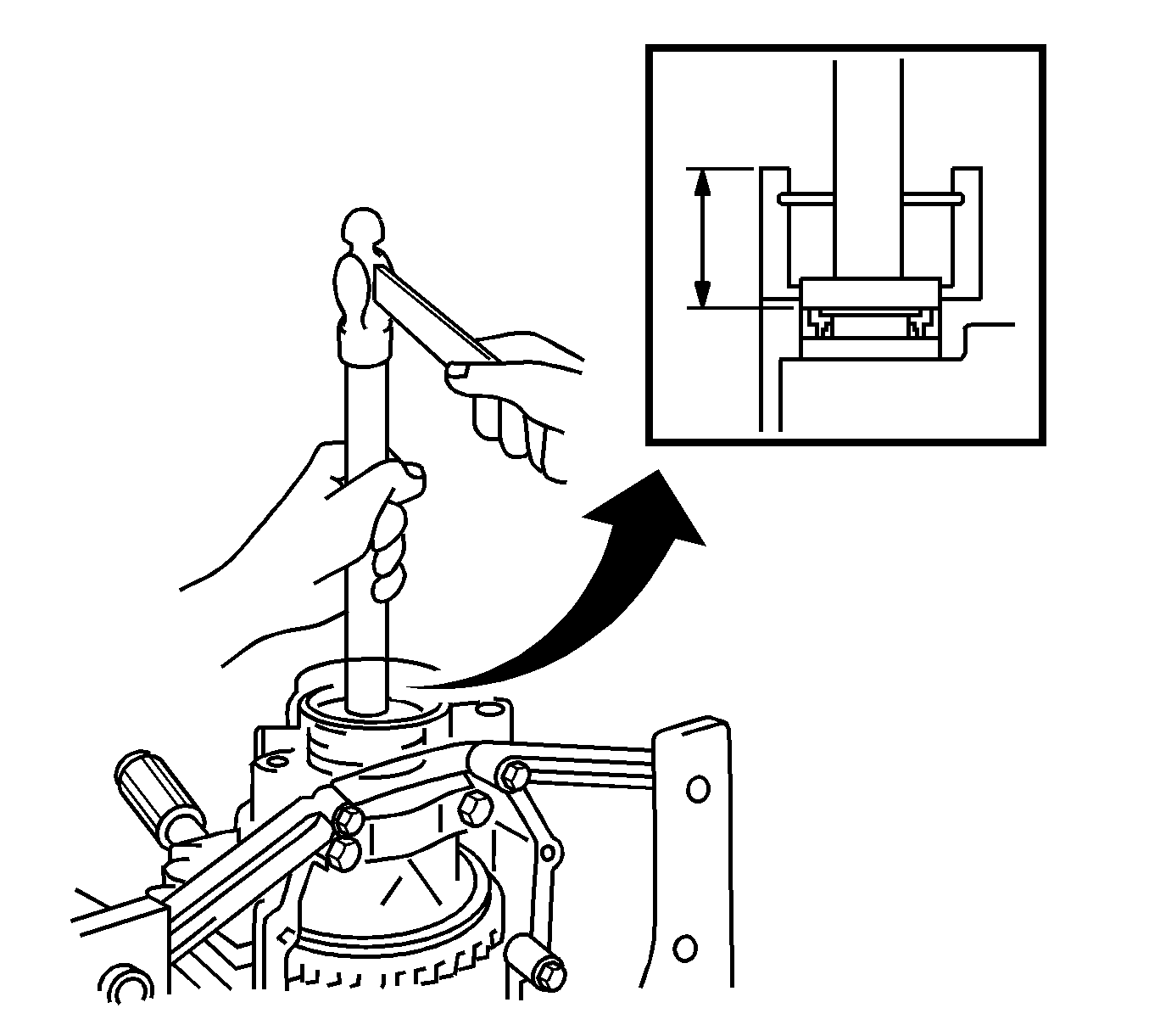
- Install the right wheel drive shaft oil seal to a depth of 33.7-34.3 mm ( 1.328-1.350 in).
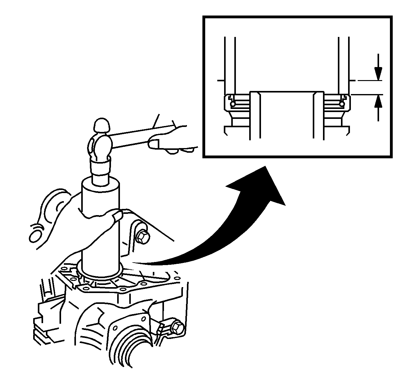
- Install the left wheel drive shaft oil seal to a depth of 9.7-10.3 mm ( 0.382-0.406 in).
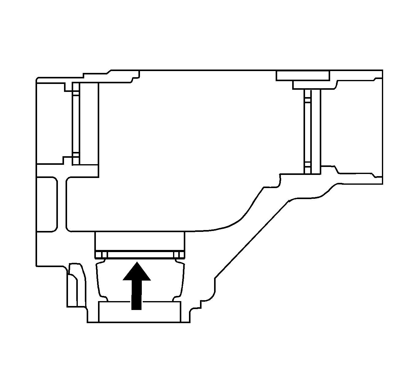
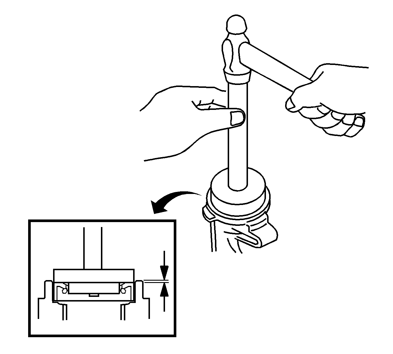
- Install the output shaft oil seal to a depth of 1.1-1.9 mm ( 0.043-0.075 in).
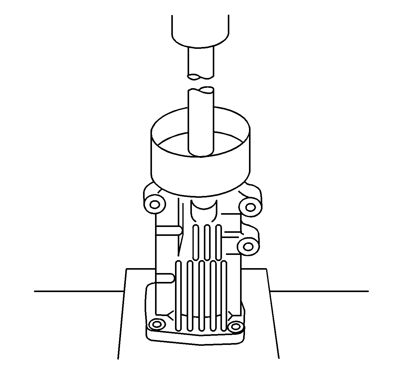
- Using a press, install the dust deflector to the extension housing.
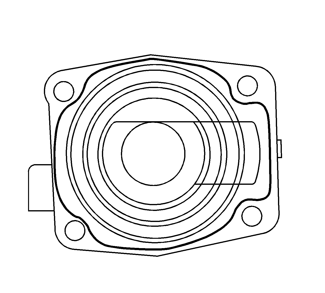
- Remove the old sealant from the transfer case extension housing mating surface.
- Remove the old sealant from the extension housing mating surface.
- Apply a 1.2 mm (0.047 in) bead of silicone sealant GM P/N 12346240 (Canadian P/N 0953493) to the extension housing.
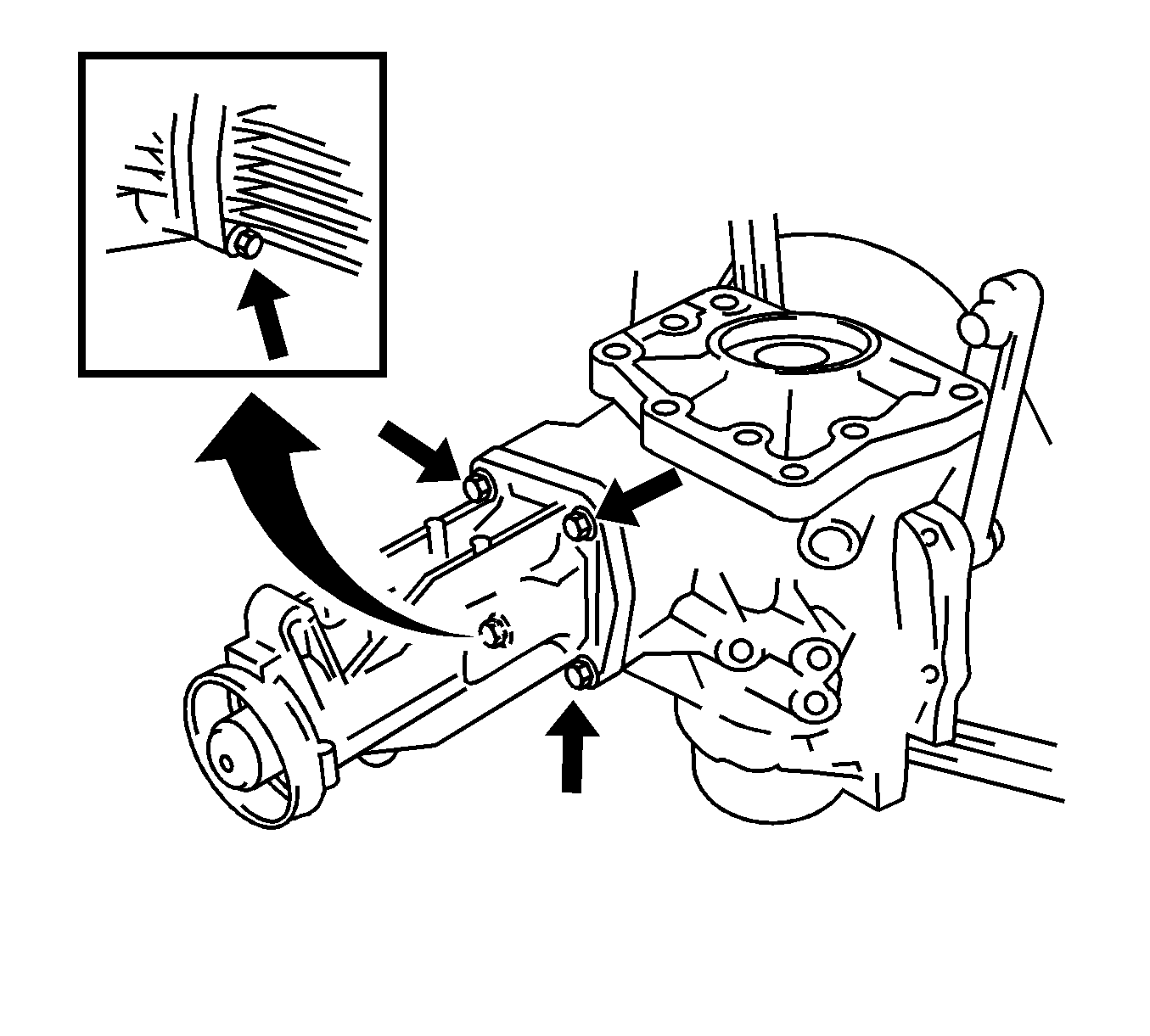
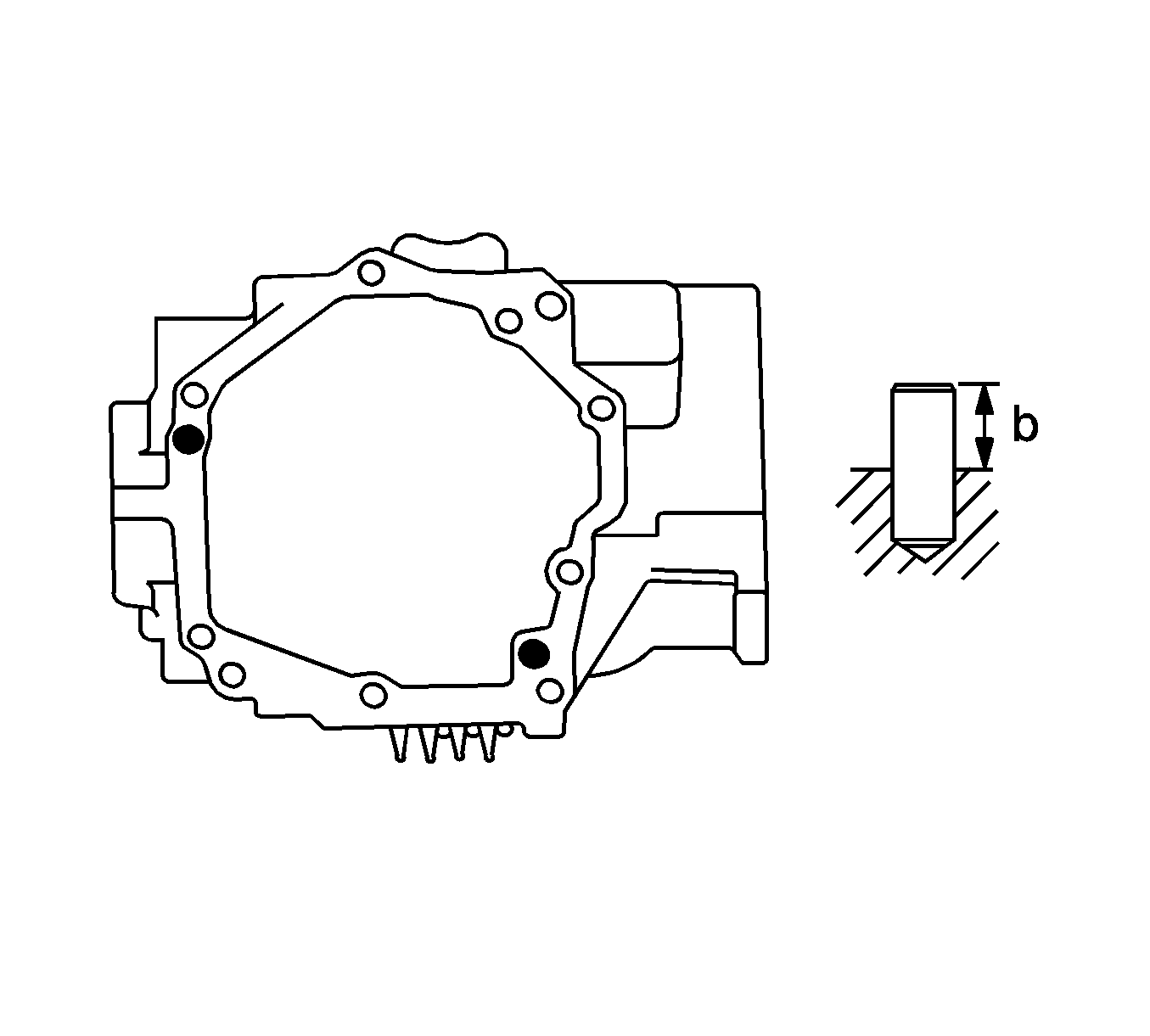
- Install the extension housing and 4 bolts to the transfer case.
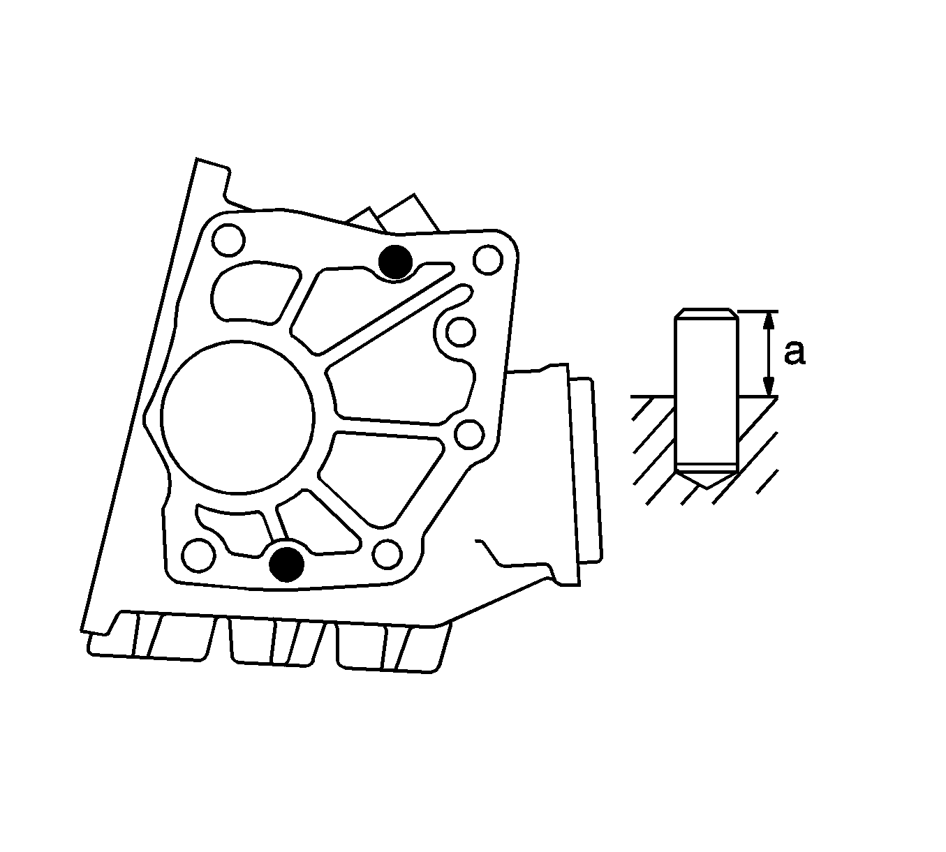
- Using a soft faced hammer, install the alignment pins until a height (A) of 10-11 mm (0.393-0.433 in) is obtained.
- Using a soft faced hammer, install the alignment pins until a height (B) of 6.5-7.5 mm (0.256-0.295 in) is obtained.
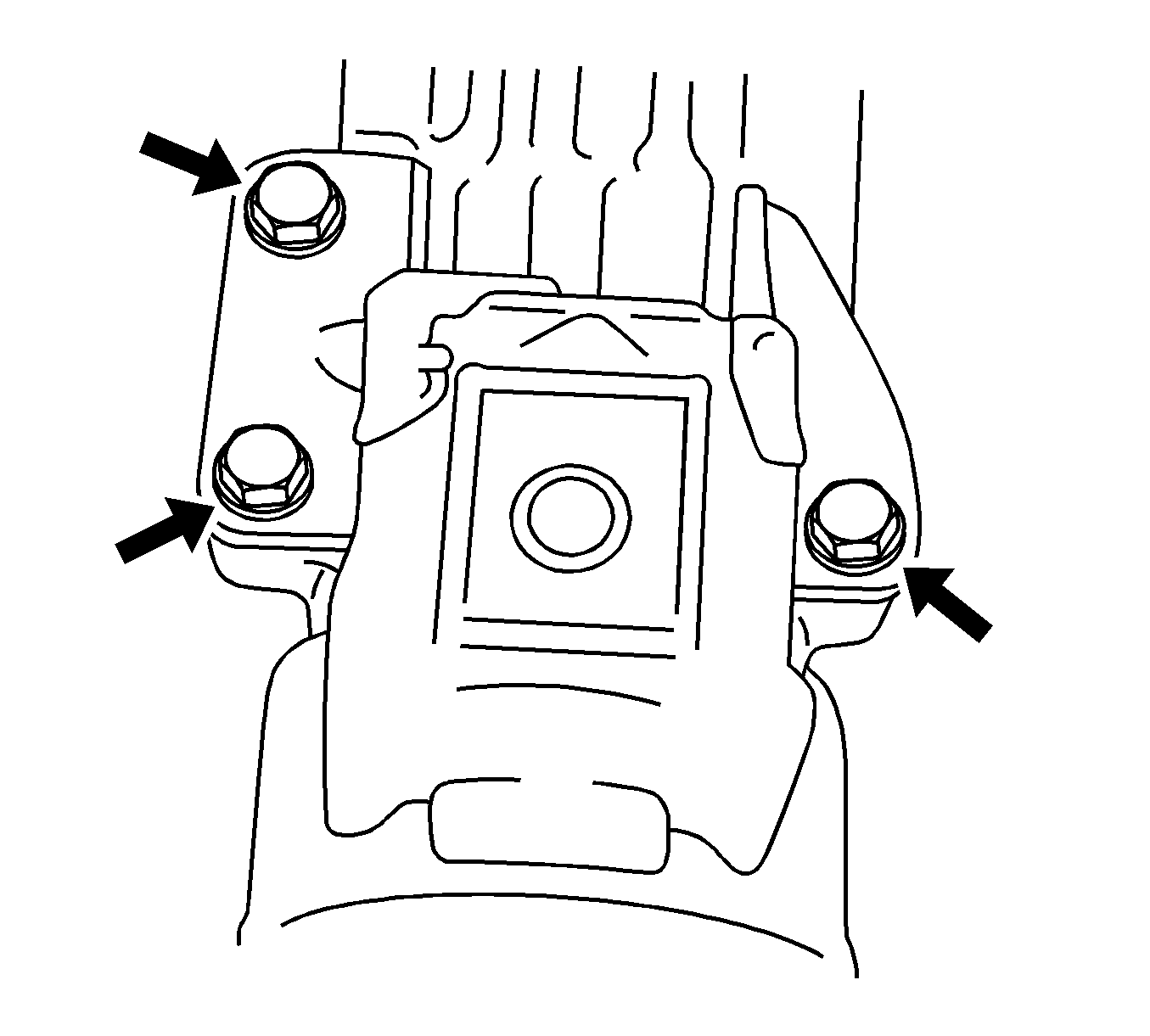
- Install the damper and 3 bolts to the transfer case.
- Install the transfer case breather plug.
- Install the transfer case breather oil deflector on the transfer case cover.
- Remove the old sealant from the transfer case cover mating surfaces.
- Apply a 1.2 mm (0.047 in) bead of silicone sealant GM P/N 12346240 (Canadian P/N 10953493) to the transfer case cover.
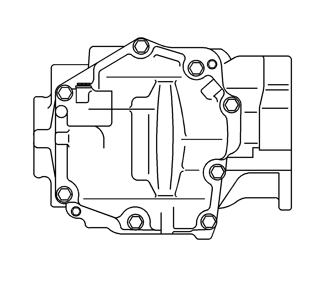
- Install the transfer case cover and the 8 bolts.
- Install the transfer case drain plug with a new gasket.
- Install the No.2 transfer case plug with a new gasket.
- Install the No.1 transfer case plug with a new gasket.
- Install the transfer case mounting studs.
Notice: Refer to Fastener Notice in the Preface section.
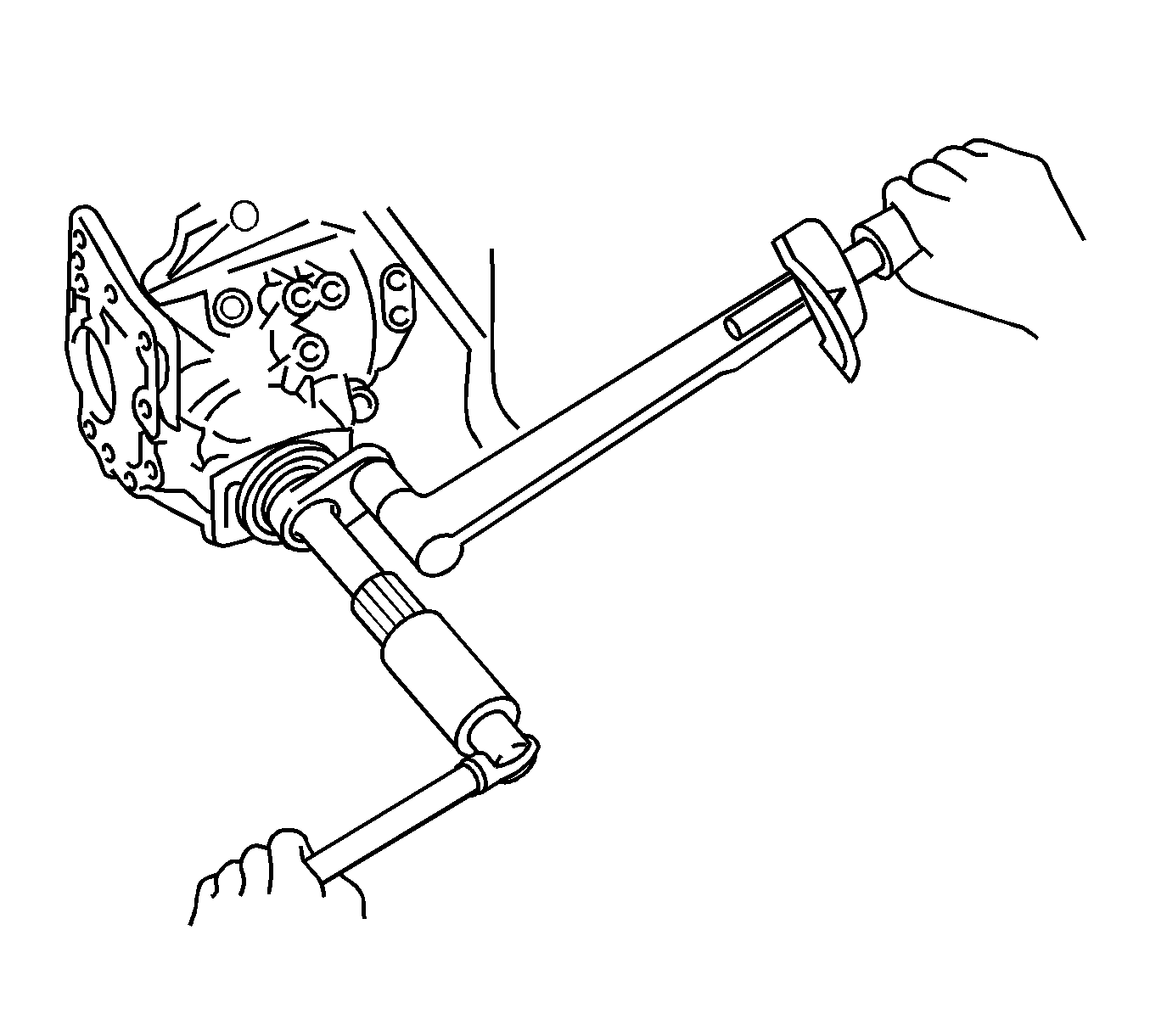
Important: Do not tighten the nut until the final adjustment of the preload, tooth contact and backlash is completed.
Tighten
Tighten to 295-403 N·m (218-297 lb ft).
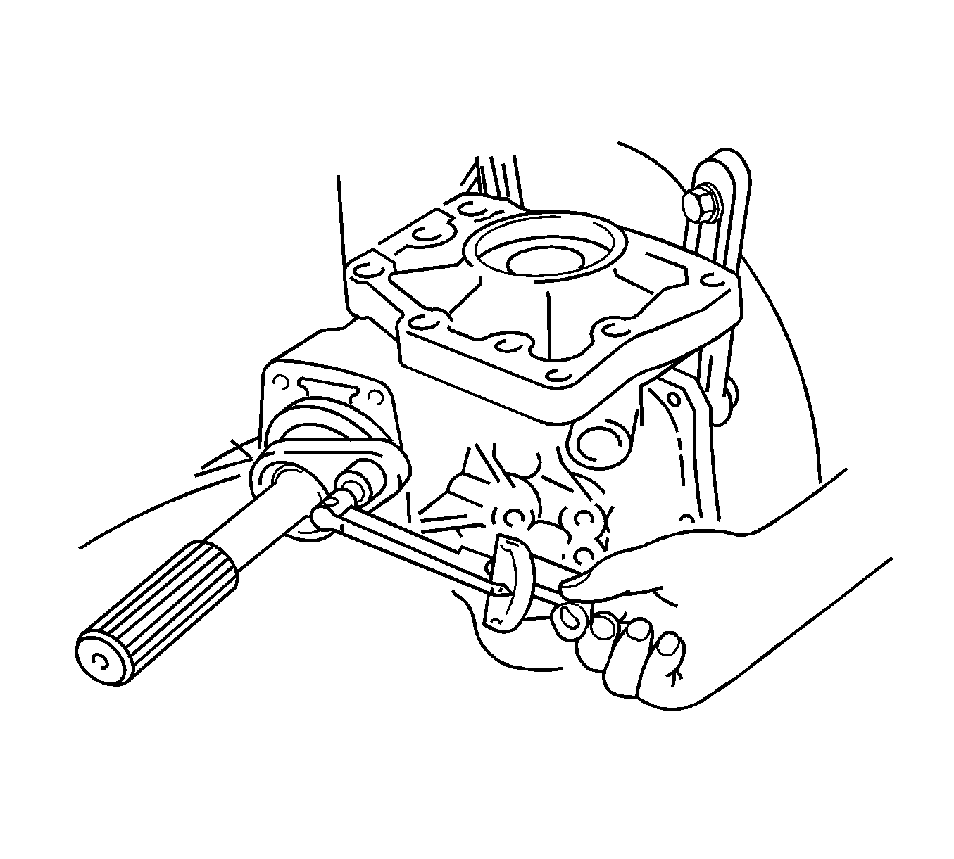
Important: If the preload is not within specification, tighten the lock nut in 5-10 degree increments until the correct preload is obtained. If the preload is more than specified, install a new spacer.
Preload
Output shaft preload at starting with a new bearing should be 0.52-0.97 N·m
(4.6-8.6 lb in) shaft preload at starting with a reused bearing
should be 0.30-0.52 N·m (2.7-4.6 lb in).
Tighten
Tighten the bolts to 78 N·m (57 lb ft).
Tighten
Tighten the bolts to 63 N·m (47 lb ft).
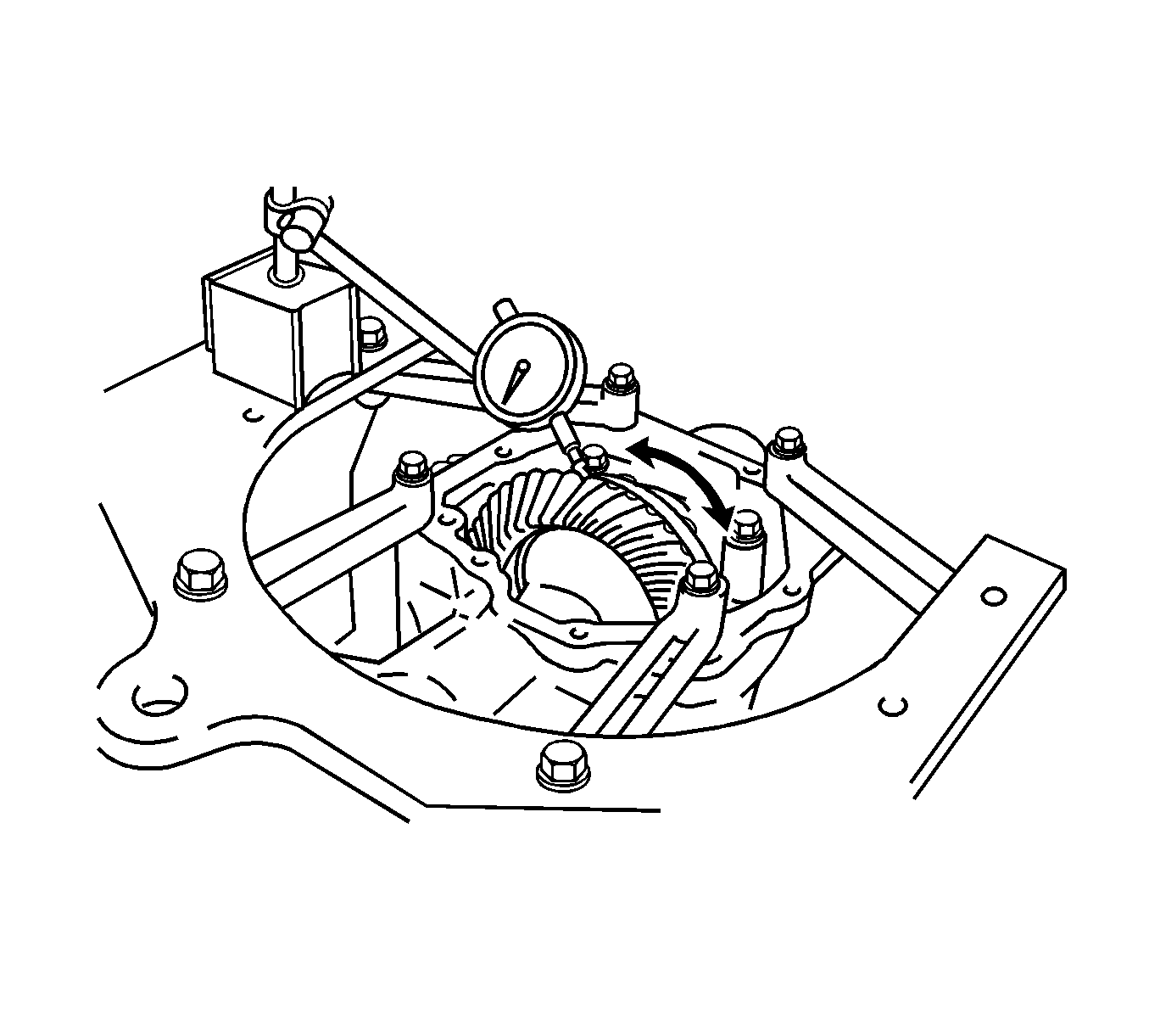
Important: Backlash should be checked in 3 different positions on the ring gear.
Backlash
Backlash should be 0.10-0.15 mm (0.0039-0.0059 in).

Preload
Output shaft total preload with a new bearing should be 0.3-0.45 N·m
(2.7-4.0 lb in). Output shaft preload at starting with a reused
bearing should be 0.19-0.33 N·m (1.7-2.9 lb in).

Important: Do not tighten the nut until the final adjustment of the preload, tooth contact and backlash is completed.
Tighten
Tighten to 295-403 N·m (218-297 lb ft).
Tighten
Tighten the 4 bolts to 26 N·m (19 lb ft).
Tighten
Tighten the 3 bolts to 26 N·m (19 lb ft).
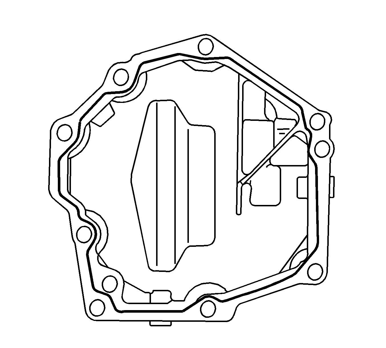
Important: The silicone sealant should be allowed to cure for 1 hour or more before filling with fluid.
Tighten
Tighten the 8 bolts to 20 N·m (14 lb ft).
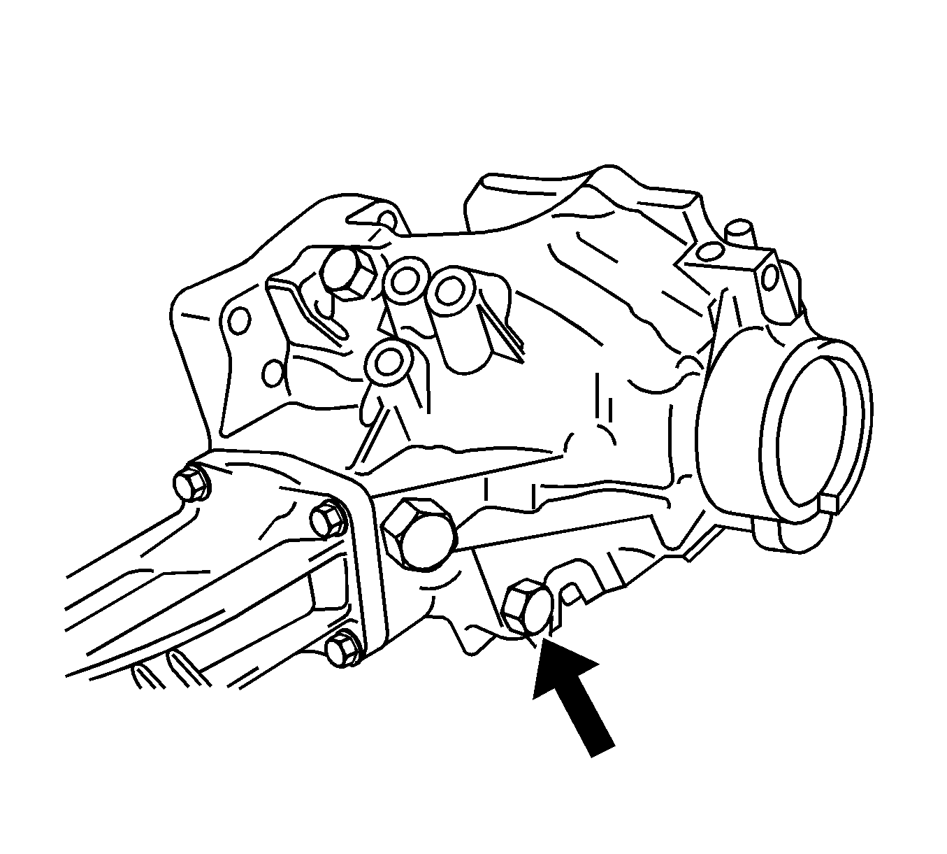
Tighten
Tighten the drain plug to 49 N·m (36 lb ft).
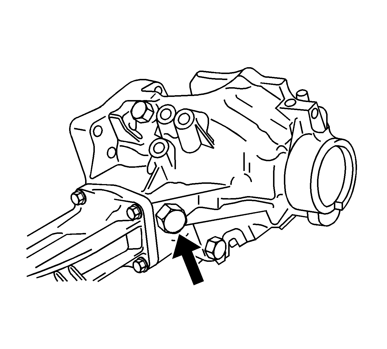
Tighten
Tighten the drain plug to 49 N·m (36 lb ft).
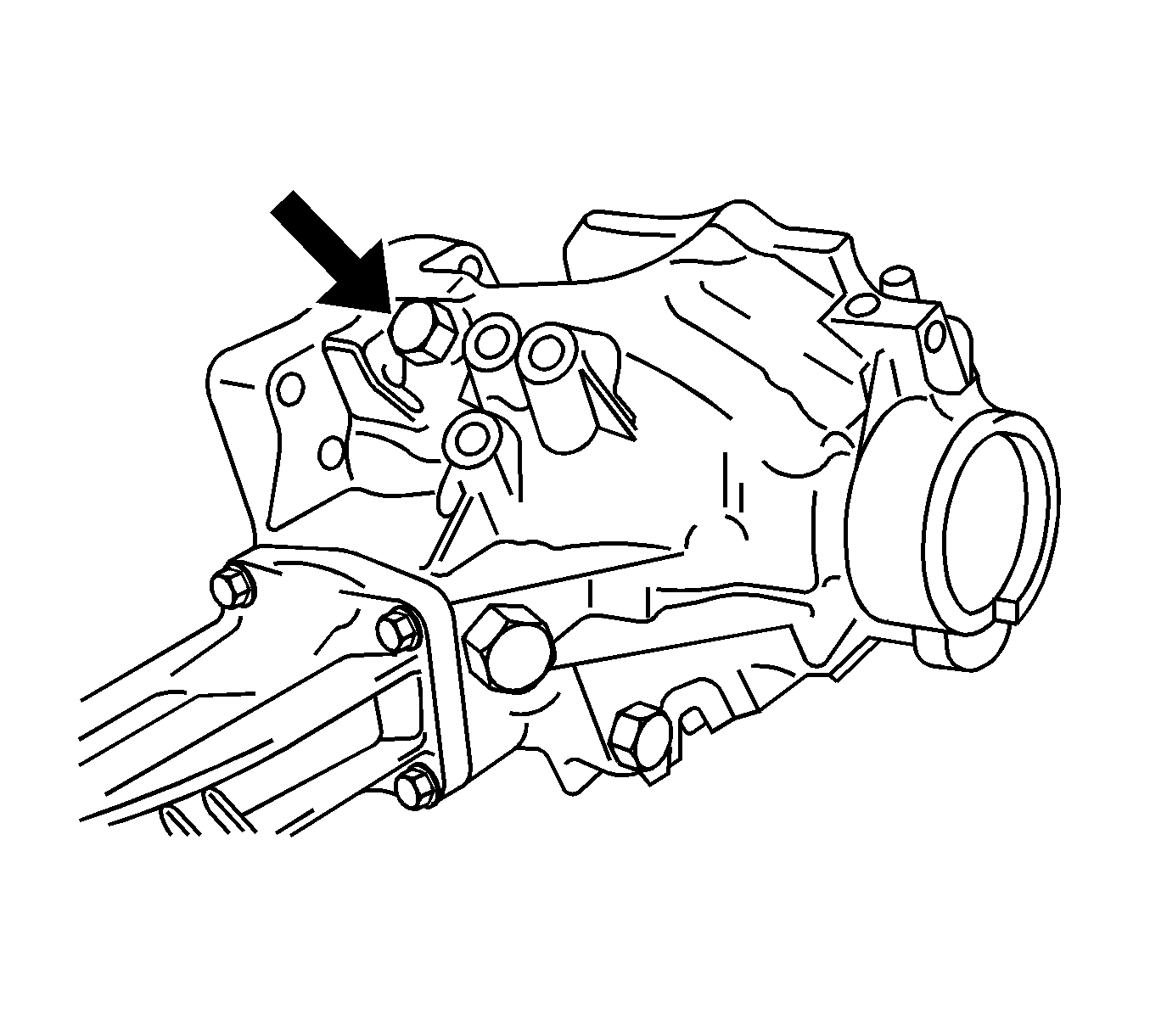
Tighten
Tighten the drain plug to 49 N·m (36 lb ft).
Tighten
Tighten the mounting studs to 39 N·m (29 lb ft).
