For 1990-2009 cars only
Exhaust Seal Replacement 1500
Removal Procedure
- Raise and support the vehicle. Refer to Lifting and Jacking the Vehicle .
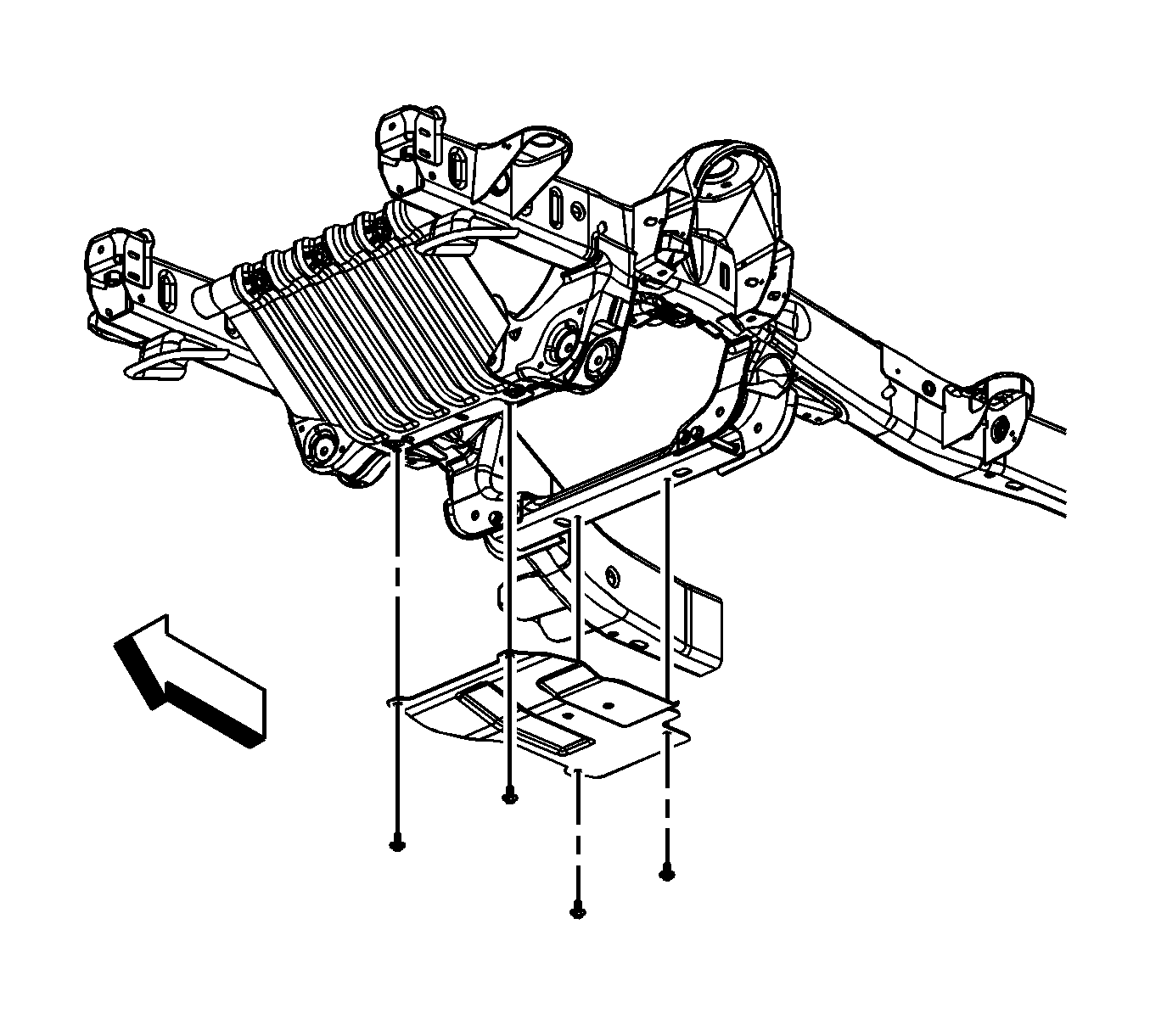
- Remove the oil pan skid plate bolts and skid plate, if equipped.
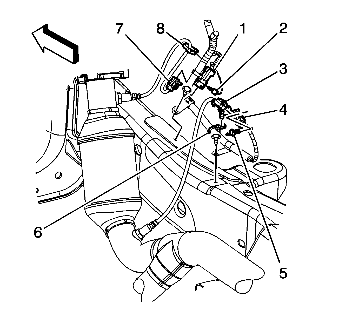
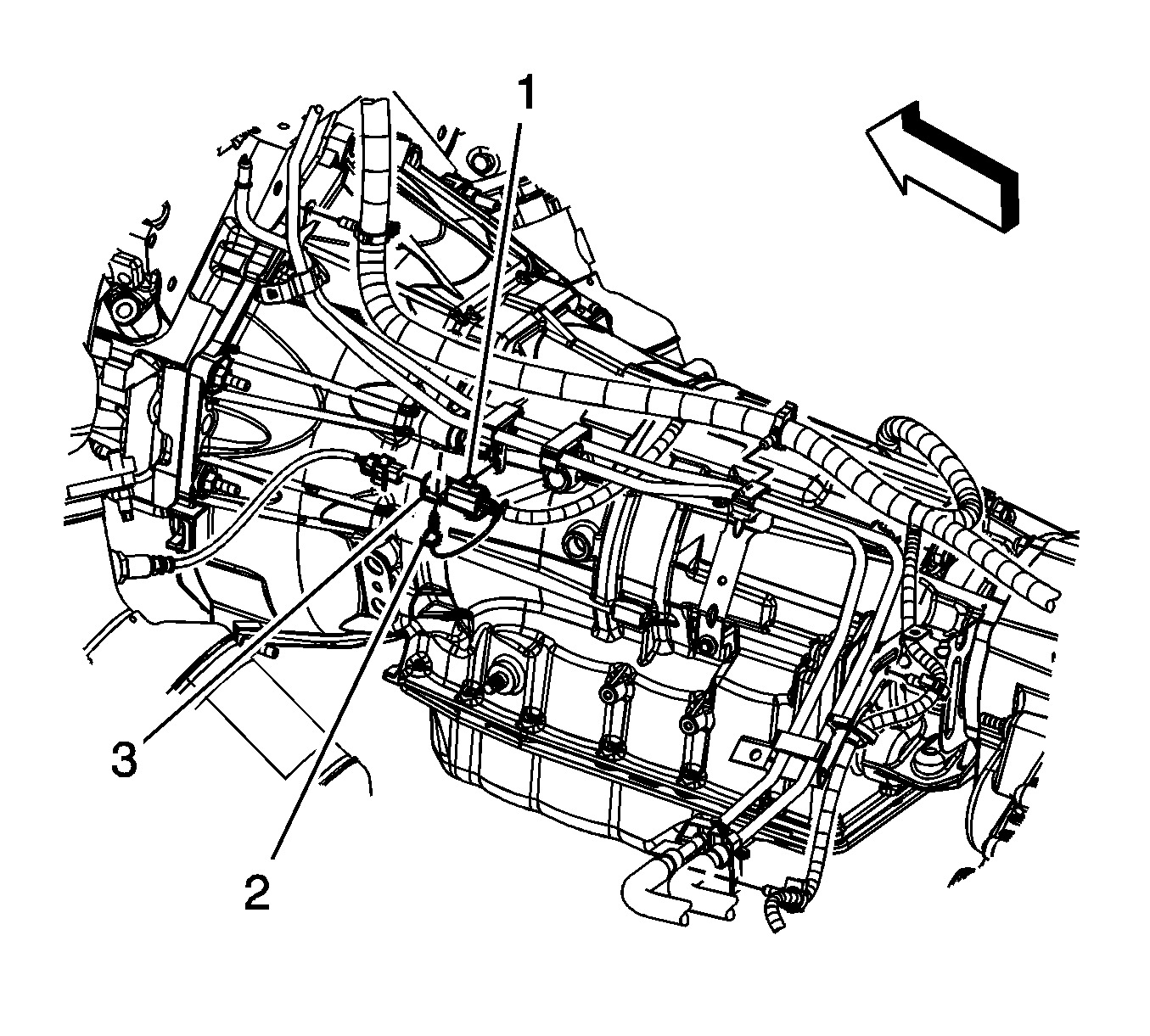
- Remove the right front connector position assurance (CPA) retainer (2).
- Disconnect the right front heated oxygen sensor (HO2S) electrical connector from the engine wiring harness electrical connector (1).
- Remove the right rear CPA retainer (4).
- Disconnect the engine wiring harness electrical connector (3) from the right rear HO2S electrical connector.
- Remove the right rear HO2S electrical connector clip from the engine harness clip (5).
- Remove the left rear CPA retainer (1).
- Disconnect the left rear HO2S electrical connector from the engine wiring harness electrical connector (3).
- For vehicles equipped with a 4L60-E/4L70-E automatic transmission perform the following steps, for vehicles equipped with a 6L80-E automatic transmission proceed to step 14.
- Remove the left front CPA retainer.
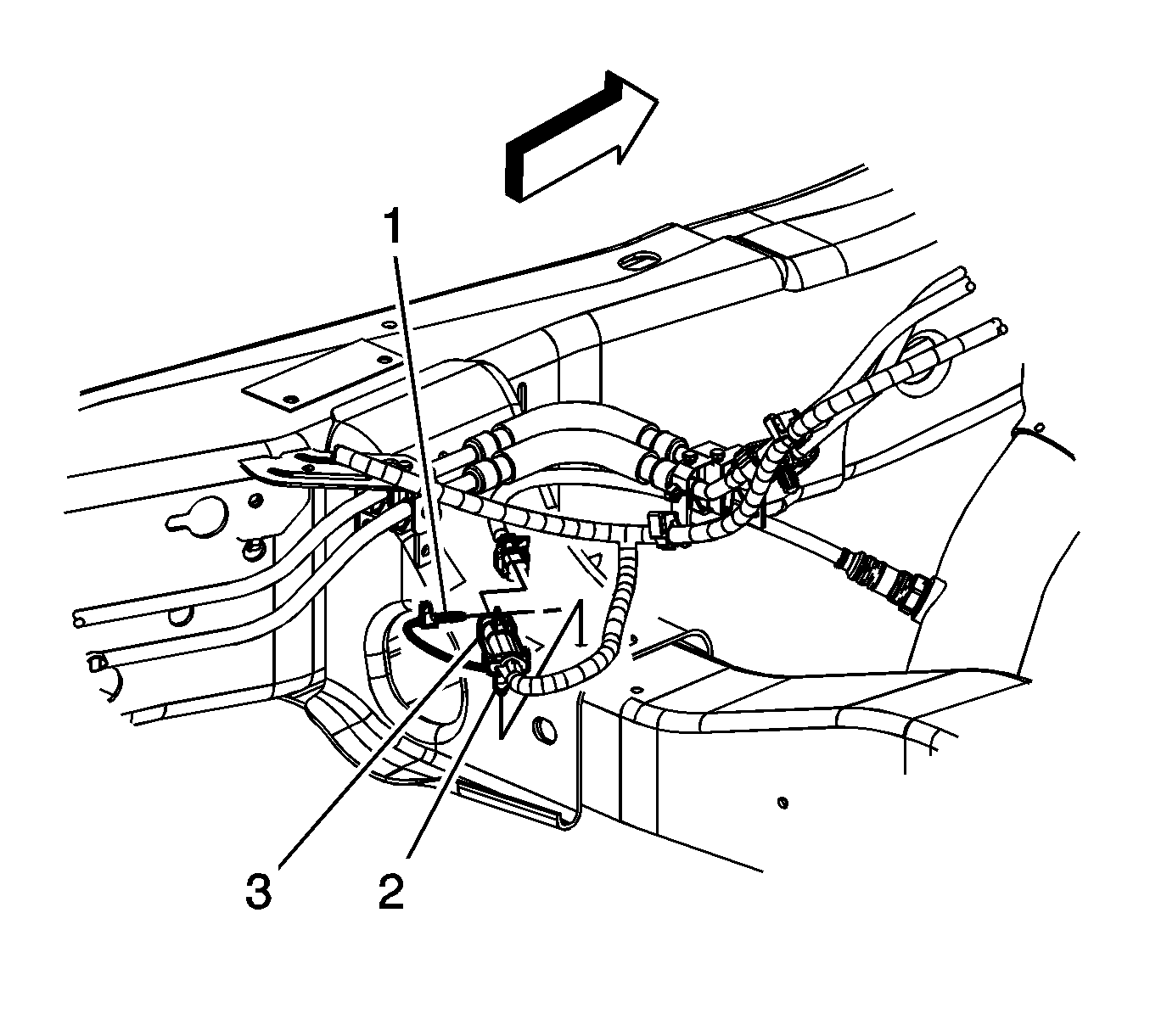
- Disconnect the engine wiring harness electrical connector (2) from the left front HO2S.
- Remove the left front HO2S electrical connector clip (1) from the fuel line clip.
- Remove the left front CPA retainer (2).
- Remove the engine wiring harness electrical connector clip (1) from the fuel line clip.
- Disconnect the engine wiring harness electrical connector (3) from the left front HO2S.
- Support the catalytic converter assembly with a suitable adjustable jack.
- Remove the HO2S. Refer to Heated Oxygen Sensor Replacement - Bank 2 Sensor 1 .
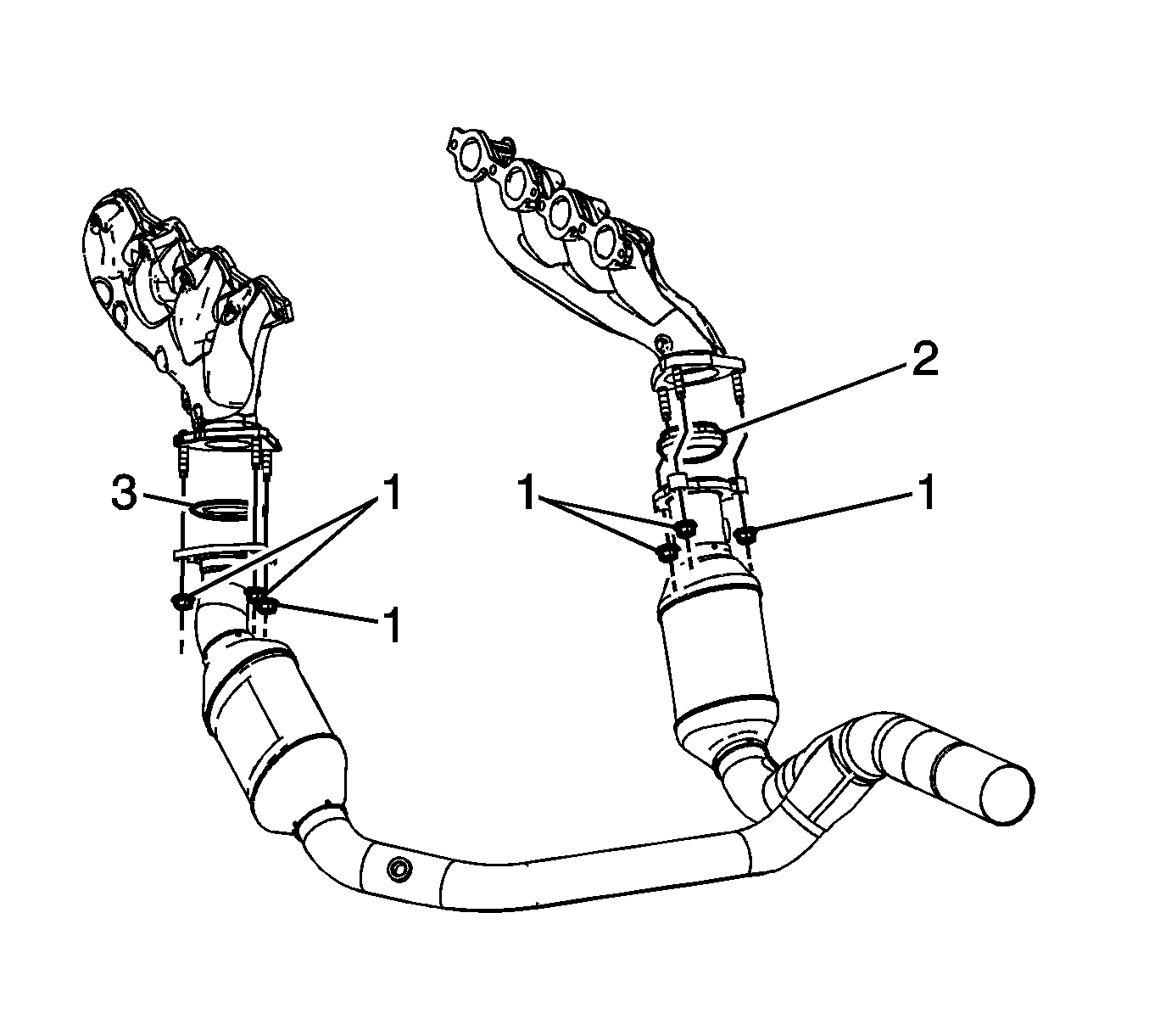
- Remove the catalytic converter to exhaust manifold nuts (1).
- Separate the catalytic converter assembly from the exhaust manifolds.
- Lower the catalytic converter assembly using the adjustable jack.
- Remove the exhaust seal (2 or 3) as required.
Installation Procedure
- Install the NEW exhaust seal (2 or 3) as required.
- Raise the catalytic converter assembly into place using the adjustable jack.
- Install the catalytic converter assembly to the exhaust manifolds.
- Install the catalytic converter to exhaust manifold nuts (1).
- Remove the adjustable jack from the catalytic converter assembly.
- Install the HO2S. Refer to Heated Oxygen Sensor Replacement - Bank 2 Sensor 1 .
- For vehicles equipped with a 4L60-E/4L70-E automatic transmission perform the following steps, for vehicles equipped with a 6L80-E automatic transmission proceed to step 10.
- Install the HO2S electrical connector clip (1) to the fuel line clip.
- Connect the engine wiring harness electrical connector (2) to the HO2S.
- Install the CPA retainer.
- Connect the engine wiring harness electrical connector (3) to the HO2S.
- Install the engine wiring harness electrical connector clip (1) to the fuel line clip.
- Install the CPA retainer (2).
- Connect the left rear HO2S electrical connector to the engine wiring harness electrical connector (3).
- Install the left rear CPA retainer (1).
- Install the right rear HO2S electrical connector clip to the engine harness clip (5).
- Connect the engine wiring harness electrical connector (3) to the right rear HO2S electrical connector.
- Install the right rear CPA retainer (4).
- Connect the right front HO2S electrical connector to the engine wiring harness electrical connector (1).
- Install the right front CPA retainer (2).
- Position the oil pan skid plate and install the oil pan skid plate bolts, if equipped.
- Lower the vehicle.

Notice: Refer to Fastener Notice in the Preface section.
Tighten
Tighten the nuts to 50 N·m (37 lb ft).


Tighten
Tighten the bolts to 28 N·m (21 lb ft).
Exhaust Seal Replacement 2500
Removal Procedure
- Raise and support the vehicle. Refer to Lifting and Jacking the Vehicle .
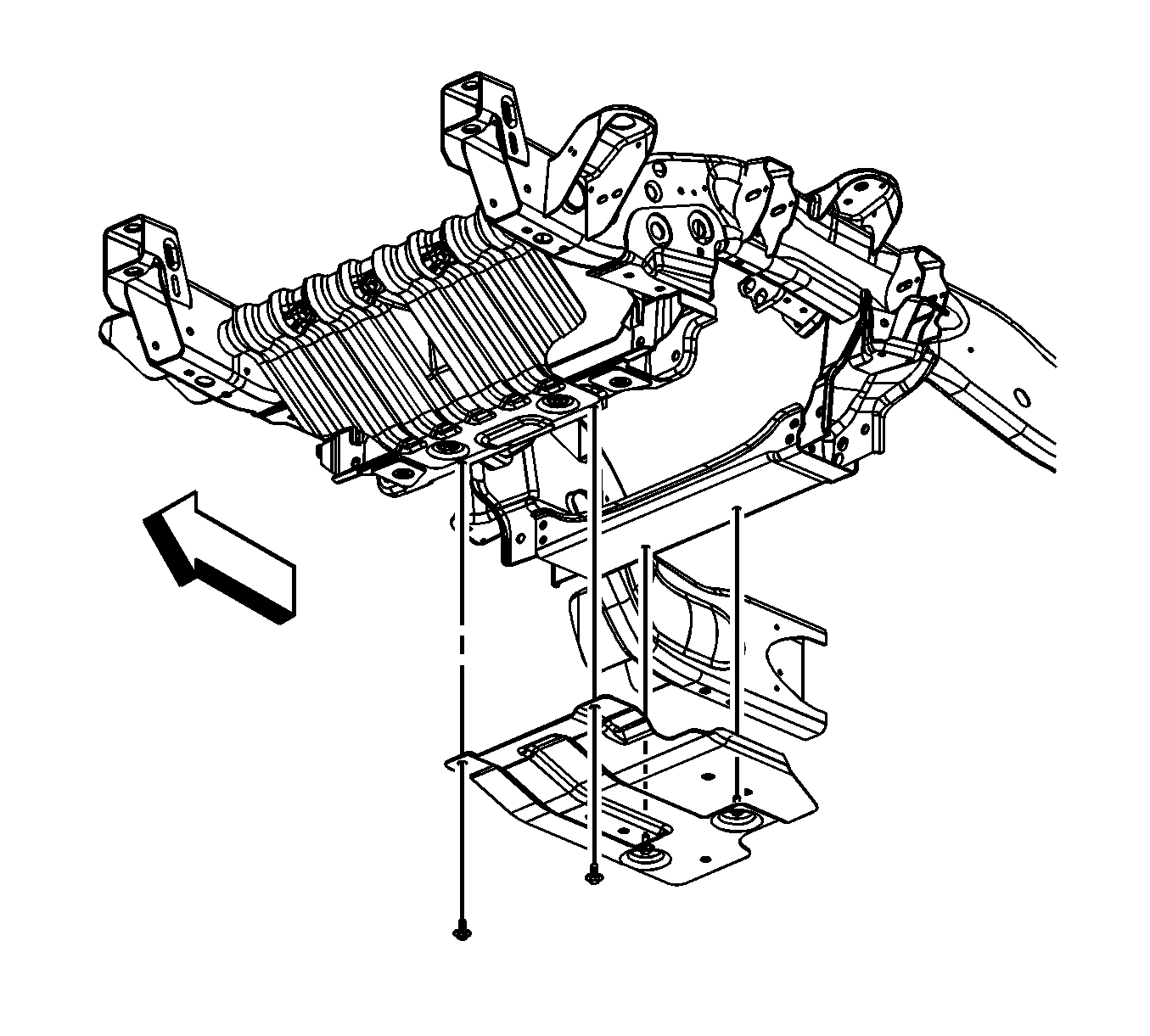
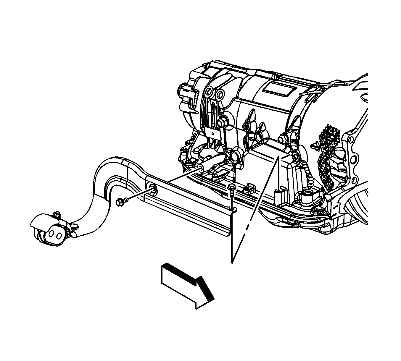
- Loosen the 2 rear oil pan skid plate bolts, remove the 2 front oil pad skid plate bolts and skid plate, if equipped.
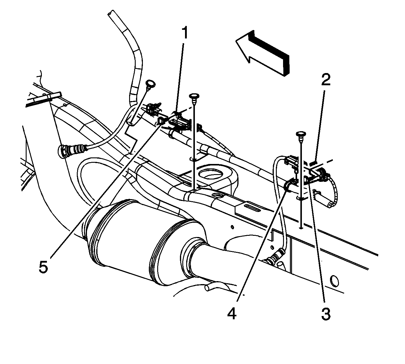
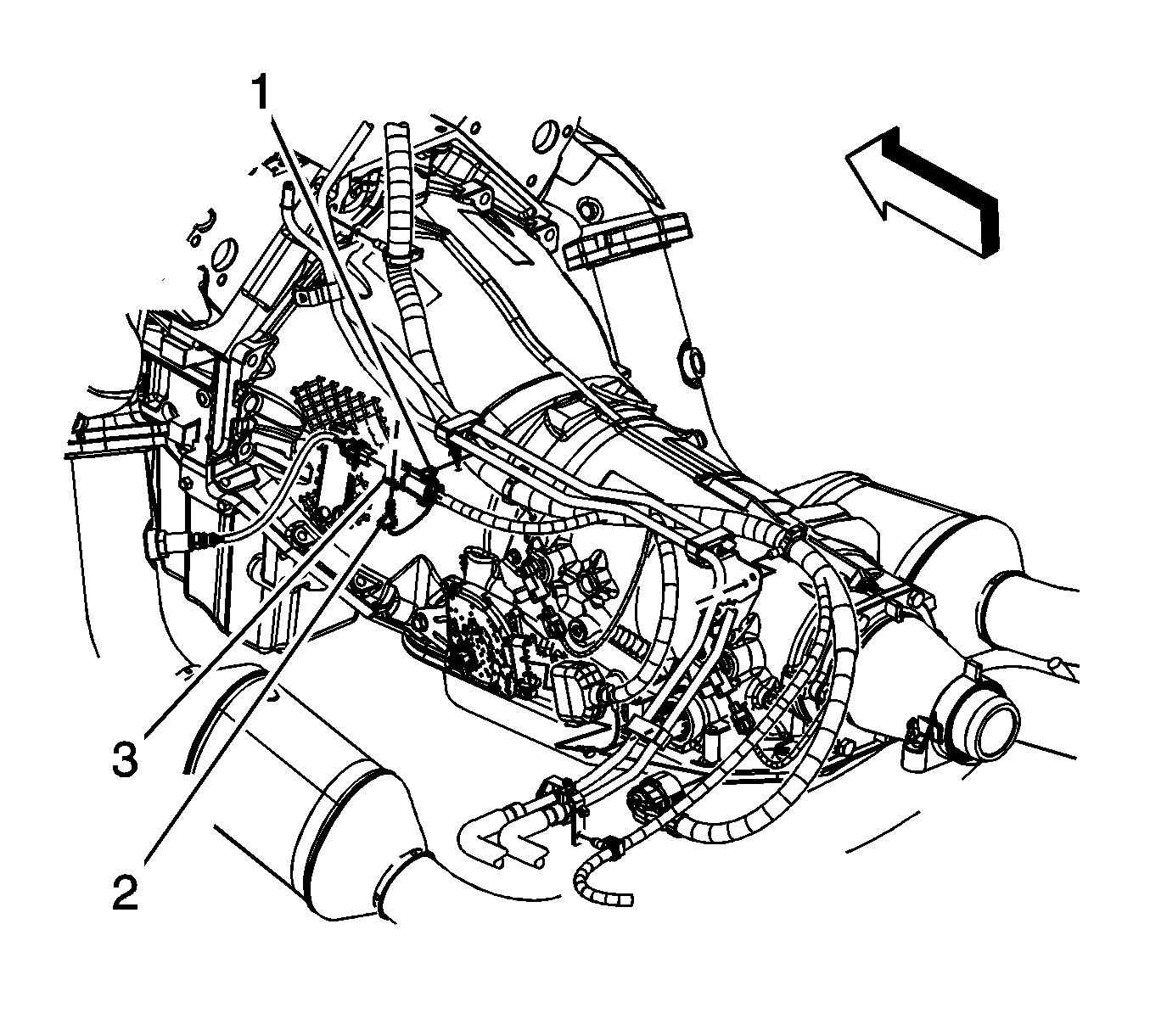
- Remove the right front connector position assurance (CPA) retainer (5).
- Disconnect the right front heated oxygen sensor (HO2S) electrical connector from the engine wiring harness electrical connector (1).
- Remove the right rear CPA retainer (3).
- Disconnect the engine wiring harness electrical connector (2) from the right rear HO2S electrical connector.
- Remove the right rear HO2S electrical connector clip from the engine harness clip (4).
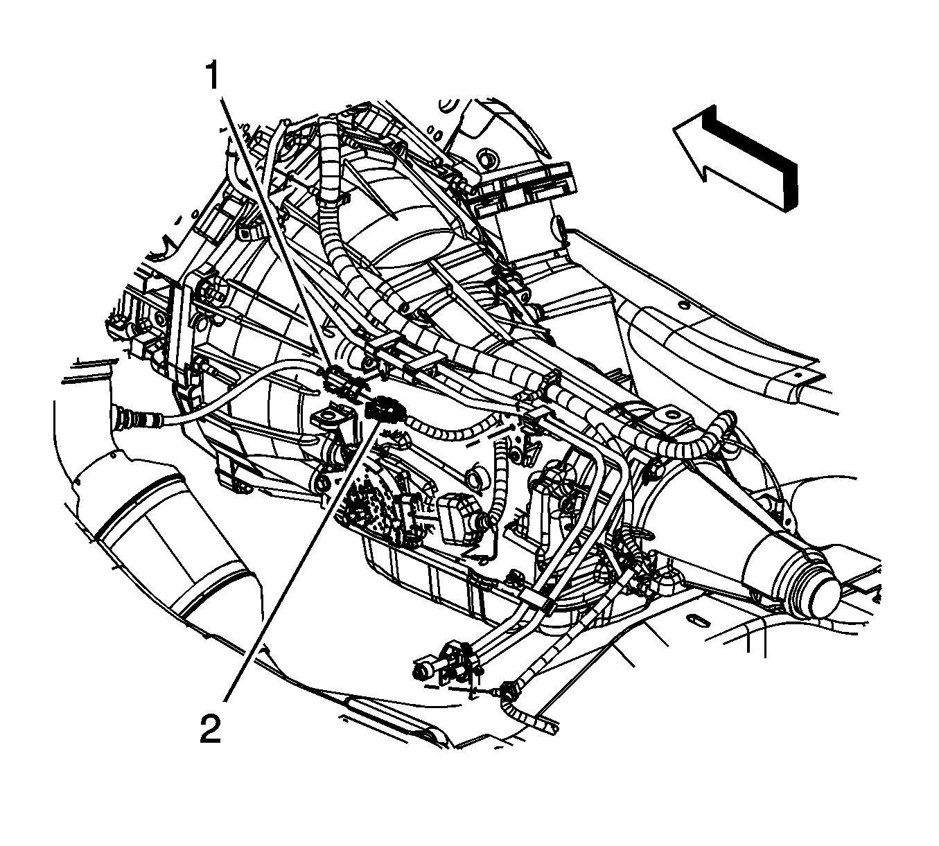
- Remove the left rear CPA retainer (1).
- Disconnect the left rear HO2S electrical connector from the engine wiring harness electrical connector (3).
- Remove the left front CPA retainer (2).
- Disconnect the left front HO2S electrical connector (2) from the engine wiring harness electrical connector (3).
- Support the catalytic converter assemblies with suitable adjustable jacks.
- Remove the exhaust pipe hanger bracket bolts.
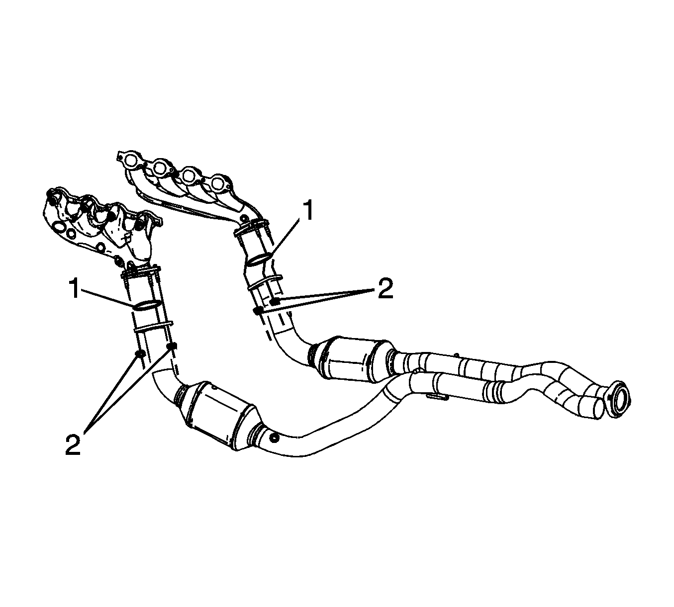
- Remove the catalytic converter to exhaust manifold nuts (2).
- Separate the catalytic converter assemblies from the exhaust manifolds.
- Lower the catalytic converter assemblies using the adjustable jacks.
- Remove the exhaust seal(s) (1) as required.

Installation Procedure
- Install the NEW exhaust seal(s) (1) as required.
- Raise the catalytic converter assemblies into place using the adjustable jacks.
- Install the catalytic converter assemblies to the exhaust manifolds.
- Install the catalytic converter to exhaust manifold nuts (2).
- Position the exhaust pipe hanger bracket to the transmission.
- Install the exhaust pipe hanger bracket bolts.
- Remove the supports from the catalytic converter assemblies.
- Connect the left front HO2S electrical connector (2) to the engine wiring harness electrical connector (3).
- Install the left front CPA retainer (2).
- Connect the left rear HO2S electrical connector to the engine wiring harness electrical connector (3).
- Install the left rear CPA retainer (1).
- Install the right rear HO2S electrical connector clip to the engine harness clip (4).
- Connect the engine wiring harness electrical connector (2) to the right rear HO2S electrical connector.
- Install the right rear CPA retainer (3).
- Connect the right front HO2S electrical connector to the engine wiring harness electrical connector (1).
- Install the right front CPA retainer (5).
- Position the oil pan skid plate and tighten until snug the 2 rear oil pan skid plate bolts, install the 2 front oil pan skid plate bolts, if equipped.
- Lower the vehicle.

Notice: Refer to Fastener Notice in the Preface section.
Tighten
Tighten the nuts to 50 N·m (37 lb ft).

Tighten
Tighten the bolts to 25 N·m (18 lb ft).


Tighten
Tighten the bolts to 28 N·m (21 lb ft).
Exhaust Seal Replacement RPO LFA
Removal Procedure
- Raise and support the vehicle. Refer to Lifting and Jacking the Vehicle .
- Remove the oil pan skid plate bolts and skid plate, if equipped.
- Remove the heated oxygen (HO2S) sensors. Refer to Heated Oxygen Sensor Replacement - Bank 1 Sensor 1, Heated Oxygen Sensor Replacement - Bank 1 Sensor 2, Heated Oxygen Sensor Replacement - Bank 2 Sensor 1 and Heated Oxygen Sensor Replacement - Bank 2 Sensor 2.
- Remove the right front connector position assurance (CPA) retainer (2).
- Disconnect the right front heated oxygen sensor (HO2S) electrical connector from the engine wiring harness electrical connector (1).
- Remove the right rear CPA retainer (4).
- Disconnect the engine wiring harness electrical connector (3) from the right rear HO2S electrical connector.
- Remove the right rear HO2S electrical connector clip from the engine harness clip (5).
- Remove the left rear CPA retainer (1).
- Disconnect the left rear HO2S electrical connector from the engine wiring harness electrical connector (3).
- Remove the catalytic converter to exhaust manifold nuts (1).
- Separate the catalytic converter assembly from the exhaust manifolds.
- Lower the catalytic converter assembly using the adjustable jack.
- Remove the exhaust seal (2 or 3) as required.


Installation Procedure
- Install the NEW exhaust seal (2 or 3) as required.
- Raise the catalytic converter assembly into place using the adjustable jack.
- Install the catalytic converter assembly to the exhaust manifolds.
- Install the catalytic converter to exhaust manifold nuts (1).
- Remove the adjustable jack from the catalytic converter assembly.
- Install the HO2S. Refer to Heated Oxygen Sensor Replacement - Bank 2 Sensor 1 .
- Connect the left rear HO2S electrical connector to the engine wiring harness electrical connector (3).
- Install the left rear CPA retainer (1).
- Install the right rear HO2S electrical connector clip to the engine harness clip (5).
- Connect the engine wiring harness electrical connector (3) to the right rear HO2S electrical connector.
- Install the right rear CPA retainer (4).
- Connect the right front HO2S electrical connector to the engine wiring harness electrical connector (1).
- Install the right front CPA retainer (2).
- Remove the heated oxygen (HO2S) sensors. Refer to Heated Oxygen Sensor Replacement - Bank 1 Sensor 1, Heated Oxygen Sensor Replacement - Bank 1 Sensor 2, Heated Oxygen Sensor Replacement - Bank 2 Sensor 1 and Heated Oxygen Sensor Replacement - Bank 2 Sensor 2.
- Position the oil pan skid plate and install the oil pan skid plate bolts, if equipped.
- Lower the vehicle.

Notice: Refer to Fastener Notice in the Preface section.
Tighten
Tighten the nuts to 50 N·m (37 lb ft).


Tighten
Tighten the bolts to 28 N·m (21 lb ft).
