Service Update for Inventory and Customer Vehicles-Vehicle Enhancements-Expires with Base Warranty

| Subject: | 08119A -- Service Update for Inventory and Customer Vehicles -- Vehicle Enhancements - Expires with Base Warranty |
| Models: | 2008 Chevrolet Tahoe |
| 2008 GMC Yukon |
| Two-Mode Hybrid Vehicles |
The service procedure in this bulletin has been revised. Review the revised procedure immediately. Discard all copies of bulletin 08119, issued April 2008.
THIS SERVICE UPDATE INCLUDES VEHICLES IN DEALER INVENTORY AND CUSTOMER VEHICLES THAT RETURN TO THE DEALERSHIP FOR ANY REASON. IT WILL EXPIRE AT THE END OF THE INVOLVED VEHICLE'S NEW VEHICLE LIMITED WARRANTY PERIOD.
Purpose
This bulletin provides a service procedure to reprogram the electronic brake control module, battery energy control module, hybrid powertrain control module, engine control module, and transmission control module, and replace the high voltage circuit impact detection (HVCID) sensor. The calibration enhancements will improve subjective powertrain performance, improve onboard diagnostics, and utilize warning lamps and a "limp home" driving mode to advise customers of certain high voltage system faults. The new sensor will increase the long term reliability of the sensor.
This service procedure should be completed as soon as possible on involved vehicles currently in dealer inventory and customer vehicles that return to the dealer for any type of service during the New Vehicle Limited Warranty coverage period.
Vehicles Involved
A list of involved vehicles currently in dealer inventory is available on the "Service Update Bulletin Information" link under the "Service" tab in DealerWorld (US) or attached to the Dealer Communication (Canada) used to release this bulletin. Customer vehicles that return for service, for any reason, and are still covered under the vehicle's base warranty, and are within the VIN breakpoints provided below, should be checked for vehicle eligibility in the appropriate system listed below.
Year | Division | Model | From | Through |
|---|---|---|---|---|
2008 | Chevrolet | Tahoe | 8R117658 | 8R245824 |
2008 | GMC | Yukon | 8R117663 | 8R245586 |
Important: Dealers are to confirm vehicle eligibility prior to beginning repairs by using the GM Vehicle Inquiry System (GMVIS). Not all vehicles within the above breakpoints may be involved.
Parts Information
Parts required to complete this service update are to be obtained from General Motors Service and Parts Operations (GMSPO). Please refer to your "involved vehicles listing" before ordering parts. Normal orders should be placed on a DRO = Daily Replenishment Order. In an emergency situation, parts should be ordered on a CSO = Customer Special Order.
Part Number | Description | Qty/ Vehicle |
|---|---|---|
25993617 | Sensor, High Voltage Circ Impact Detection | 1 |
Service Procedure
Programming the Hybrid Control Modules
Do not attempt to order the calibration number from GMSPO. The calibration numbers required for this service procedure are programmed into control modules via a Multiple Diagnostic Interface (MDI) and TIS2WEB with the calibration update. Use TIS2WEB on or after 04/28/08 to obtain the calibration. If you cannot access the calibration, call the Techline Customer Support Center and it will be provided.
Service Programming System (SPS)
For step-by-step programming instructions, please refer to SI and the Techline Information System (TIS) terminal.
Review the information below to ensure proper programming protocol.
Important:
• DO NOT program a control module unless you are directed by a service procedure or you are directed by a General Motors Corporation service bulletin. Programming a control module at any other time will not permanently correct a customer's concern. • It is essential that the Multiple Diagnostic Interface (MDI) and the TIS terminal are equipped with the latest software before performing (SPS). • Due to the time requirements of programming a controller, it is recommended that an external power source be used to maintain system voltage. Stable battery voltage is critical during programming. Any fluctuation, spiking, over voltage or loss
of voltage will interrupt programming. To ensure trouble-free programming, GM recommends using one of the following external power sources: - A Midtronic PCS charger. - Battery voltage must be maintained above 12 volts during the entire reprogramming event or programming may be interrupted. The programming event will take approximately 45 minutes to complete. - Some modules will require additional programming/setup events performed before or after programming. - Some vehicles may require the use of a CANDi module for programming. - Review the appropriate service information for these procedures. - DTCs may set during programming. Clear DTCs after programming is complete. - Clearing powertrain DTCs will set the Inspection/Maintenance (I/M) system status indicators to NO.
Ensure the following conditions are met before programming a control module:
| • | FlexFuel (E85) Vehicles |
| - | The fuel composition learn function is inactive. Programming with the fuel composition learn active will result in fuel trim DTCs. |
| - | If necessary, drive the vehicle until the scan tool indicates that the fuel composition learn is inactive. |
| • | Vehicle System Voltage |
| - | There is not a charging system concern. All charging system concerns must be repaired before programming a control module. |
| - | Battery voltage is greater than 12 volts but less than 16 volts. The battery must be fully charged before programming the control module. |
| - | Turn OFF or disable any system that may put a load on the vehicle’s battery, such as the following components: |
| - | Twilight sentinel |
| - | Interior lights |
| - | Daytime running lights (DRL) - Applying the parking brake, on most vehicles, disables the DRL system |
| - | Heating, ventilation, and air conditioning (HVAC) systems |
| - | Engine cooling fans, radio, etc. |
| • | The ignition switch must be in the proper position. SPS prompts you to turn ON the ignition, with the engine OFF. DO NOT change the position of the ignition switch during the programming procedure, unless instructed to do so. |
| • | Make certain all tool connections are secure, including the following components and circuits: |
| - | The RS-232 communication cable port. |
| - | The connection at the data link connector (DLC) |
| - | The voltage supply circuits |
| • | DO NOT disturb the tool harnesses while programming. If an interruption occurs during the programming procedure, programming failure or control module damage may occur. |
| • | DO NOT turn OFF the ignition if the programming procedure is interrupted or unsuccessful. Ensure that all control module and DLC connections are secure and the TIS terminal operating software is up to date. Attempt to reprogram the control module. If the control module cannot be programmed, replace the control module. |
- Verify that 12-volt battery has a battery charge of 12 to 16 volts. The battery must be able to maintain a charge during programming. Only use approved Midtronics 165-PCS charger or equivalent, to maintain proper battery voltage during programming.
- Reprogram the hybrid control modules. Refer to SI and Service Programming System (SPS) documentation for programming instructions, if required.
- After completing the sequential programming events, clear all DTCs using the MDI, then cycle the ignition OFF for 30 seconds.
- Remove the MDI and connect the Tech 2® scan tool.
- Perform an EBCM relearn procedure using the Tech 2® scan tool. Refer to SI and Service Programming System (SPS) documentation for programming instructions, if required.
- After performing the EBCM relearn procedure, first clear EBCM DTC codes and then clear ECM codes.
- Start the vehicle. Ensure no DTCs are present. Also verify that no instrument panel service telltale symbols are illuminated.
- Perform High Voltage Circuit Impact Detection Sensor Replacement procedure in this bulletin.
| Important: Select J2534 MDI and Reprogram ECU from the Select Diagnostic Tool and Programming Process screen. The J2534 MDI will reprogram the modules in less time than the Tech 2® scan tool. Do NOT use a Tech 2® to program the hybrid control modules. |
| 2.1. | Connect the MDI to the vehicle. |
| 2.2. | Select SEQ HCP/ECM/TCM/BECM/EBCM Sequential Programming from the Supported Controllers screen. |
| 2.3. | Follow the on-screen instructions. |
Important: If the vehicle was driven into the service area, then the 300-volt battery is sufficiently charged. Ignore the TIS2WEB screen that instructs the technician to charge the 300-volt battery system. Select Next and continue. It is important to monitor the status of the programming event. Five hybrid control modules will be programmed sequentially. During the programming events, the headlights of the vehicle will turn on after each module has been programmed. Turn off the headlights after each programming event.
High Voltage Circuit Impact Detection Sensor Replacement
- Turn the ignition switch to the off/lock position and remove the ignition key. Do not insert the ignition key into the ignition until the procedure has been completed.
- Lift and support the vehicle. Refer to Lifting and Jacking the Vehicle in SI.
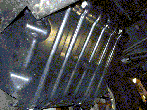
- Remove the engine shield from the vehicle.
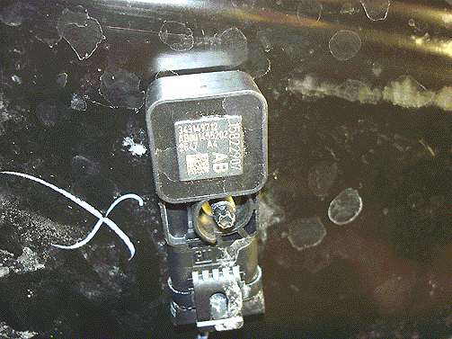
- Disconnect the electrical connector from the high voltage circuit impact detection sensor.
- Install a new high voltage circuit impact detection sensor and bolt.
- Install the engine shield to the vehicle. Tighten the four bolts to 20 N·m (15 lb ft).
- Lower the vehicle.


Important: The bolt is an integral part of the sensor and should remain with the sensor.
| 4.1. | Loosen the sensor bolt. |
| 4.2. | Remove the sensor from the vehicle. |

| 5.1. | Tighten the sensor bolt to 10 N·m(89 lb in). |
| 5.2. | Install the electrical connector to the high voltage circuit impact detection sensor. |

Claim Information
For vehicles repaired under this service update, use:
Labor Operation | Description | Labor Time |
|---|---|---|
V1814 | Reprogram Hybrid Control Modules and Replace HVCID Sensor | 1.3 |
