Description
In order to provide the best possible combination of driveability, fuel economy, and emission control, the powertrain control module (PCM) uses a Closed Loop air/fuel metering system. The PCM monitors the heated oxygen sensor (HO2S) signal voltage and, when in Closed Loop, adjusts the fuel delivery based on the HO2S signal voltage. Changes in fuel delivery will be indicated by the long term and the short term fuel trim values that are displayed on the scan tool. The ideal fuel trim value is around 0 percent. The PCM will add fuel when the heated oxygen sensor signal is indicating a lean condition. Additional fuel is indicated by fuel trim values that are more than 0 percent. The PCM will reduce the amount of fuel delivered when a rich condition is indicated by the HO2S. fuel trim values less than 0 percent indicate a reduction in fuel. A fuel trim DTC can be set when the exhaust emissions reach excessive levels because of a lean or rich condition.
Conditions for Running the DTC
| • | The barometric pressure (BARO) is more than 75 kPa. |
| • | The engine coolant temperature (ECT) is between -8°C and +95°C (18°F-203°F) at engine start up. |
| • | The intake air temperature (IAT) is between -8°C and +60°C (18°F-140°F) at engine start up. |
Conditions for Setting the DTC
Any of the following conditions are detected while the ECT is less than 110°C (230°F):
| • | The short term fuel trim is less than or equal to -11 percent in 128 firing events. |
| • | The long term fuel trim is less than or equal to -11 percent in 128 firing events. |
| • | The total fuel trim is less than or equal to -30 percent in 128 firing events. |
Action Taken When the DTC Sets
| • | The PCM illuminates the malfunction indicator lamp (MIL) after 2 consecutive ignition cycles in which the diagnostic runs with the fault active. |
| • | The PCM records the operating conditions at the time the diagnostic fails. This information is stored in the Freeze Frame buffer. |
Conditions for Clearing the MIL/DTC
| • | The MIL turns off after 3 consecutively passing trips without a fault present. |
| • | A history DTC will clear after 40 consecutive warm-up cycles without a fault. |
| • | Perform the scan tool Clear DTC Information function in order to clear the DTC. |
Diagnostic Aids
Check for any of the following conditions:
| • | If any DTCs other than fuel trim P0171, P0172, misfire P0300 to P0304 and EGR P0400 are set, diagnose those DTCs first. |
| • | Check for a restriction in the inlet air passage. A duct or inlet hose that collapses when hot or that is blocked by debris can cause DTC P0172 to set. |
| • | Check for the correct fuel pressure. The fuel system will be rich if the fuel pressure is too high. In order to determine the cause of DTC P0171 monitoring the fuel pressure while driving the vehicle at various road speeds may be necessary. Refer to Fuel System Diagnosis . |
| • | A malfunctioning MAF sensor. |
| • | Check for a damaged wiring harness. Inspect the wiring harness for damage. If the harness appears to be OK, observe the HO2S 1 display on the scan tool while moving the connectors and the wiring harnesses related to the sensor. A change in the display will indicate the location of the fault. |
| • | Check for a contaminated oxygen sensor. Silicone and other contaminants can cause the oxygen sensor to provide false exhaust oxygen content readings. If contamination is found, determine the cause and correct the condition before replacing the HO2S. |
| • | Inspect the HO2S 1 for water intrusion into the wiring harness and the sensor housing. Water can create a short to voltage in the HO2S signal circuit causing a false rich indication. |
| • | Check the HO2S 1 and the MAF sensor for a faulty electrical connection to the PCM. |
If a DTC P0172 is intermittent, driving the vehicle under the following conditions can verify whether the fault is present. Perform the scan tool Clear DTC Information function. Road test the vehicle while monitoring the DTC P0172 diagnostic on the scan tool under the Not Ran Since Code Cleared selection in the DTC Information menu. If a DTC P0172 appears in the Not Ran Since Code Cleared list, the P0172 diagnostic has not yet run. When the DTC P0172 does not appear in the Not Ran Since Code Cleared list, the P0172 diagnostic has run. If the MIL is NOT illuminated, and there is no Pending DTC Status in DTC Information, the P0172 diagnostic has passed. DTCs MUST be cleared in order to view the Current Status of the Not Ran Since Code Cleared list. DO NOT forget that the Not Ran Since Code Cleared list only indicates that the test has run, not whether the test passed or failed. The DTC Information screen must be checked for Current or Pending status in order to determine the outcome of the diagnostic test involved.
If a DTC P0172 cannot be duplicated, the information included in the Freeze Frame data can be useful in determining vehicle operating conditions when the DTC was first set.
Test Description
The numbers below refer to the step numbers in the diagnostic table.
-
The Powertrain OBD System Check prompts the technician to complete some basic checks and store the freeze frame data on the scan tool if applicable. This creates an electronic copy of the data taken when the fault occurred. The information is then stored in the scan tool for later reference.
-
This step determines if the fault is present.
-
This step checks for excess fuel from the fuel injectors. The fault may be a fuel injector or the fuel injector electrical circuit.
Step | Action | Value(s) | Yes | No | ||||||||
|---|---|---|---|---|---|---|---|---|---|---|---|---|
Did you perform the Powertrain On-Board Diagnostic (OBD) System Check? | -- | |||||||||||
2 |
Is the scan tool display more than the specified value? | -11% | ||||||||||
Was the scan tool display more than the specified value while operating the vehicle within the Freeze Frame conditions? | -30% | Go to Diagnostic Aids | ||||||||||
4 |
Was a repair necessary? | -- | ||||||||||
5 |
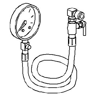
Is the fuel pressure within the specified range? | 250 - 300 kPa (36 - 43 psi) | Go to Fuel System Diagnosis | |||||||||
6 |
Was a problem found and repaired? | -- | ||||||||||
7 |
Important: Repair the cause of the contamination before replacing a contaminated HO2S. Did the HO2S 1 require replacement? | -- | ||||||||||
Check the fuel injectors for any of the following conditions:
Did the fuel injectors pass all the checks? | -- | Go to Diagnostic Aids | ||||||||||
9 | Replace any faulty fuel injectors. Refer to Fuel Injector and Fuel Rail Replacement . Is the action complete? | -- | -- | |||||||||
10 |
Are any DTCs displayed on the scan tool? | -- | System OK |
