GM Service Manual Online
For 1990-2009 cars only

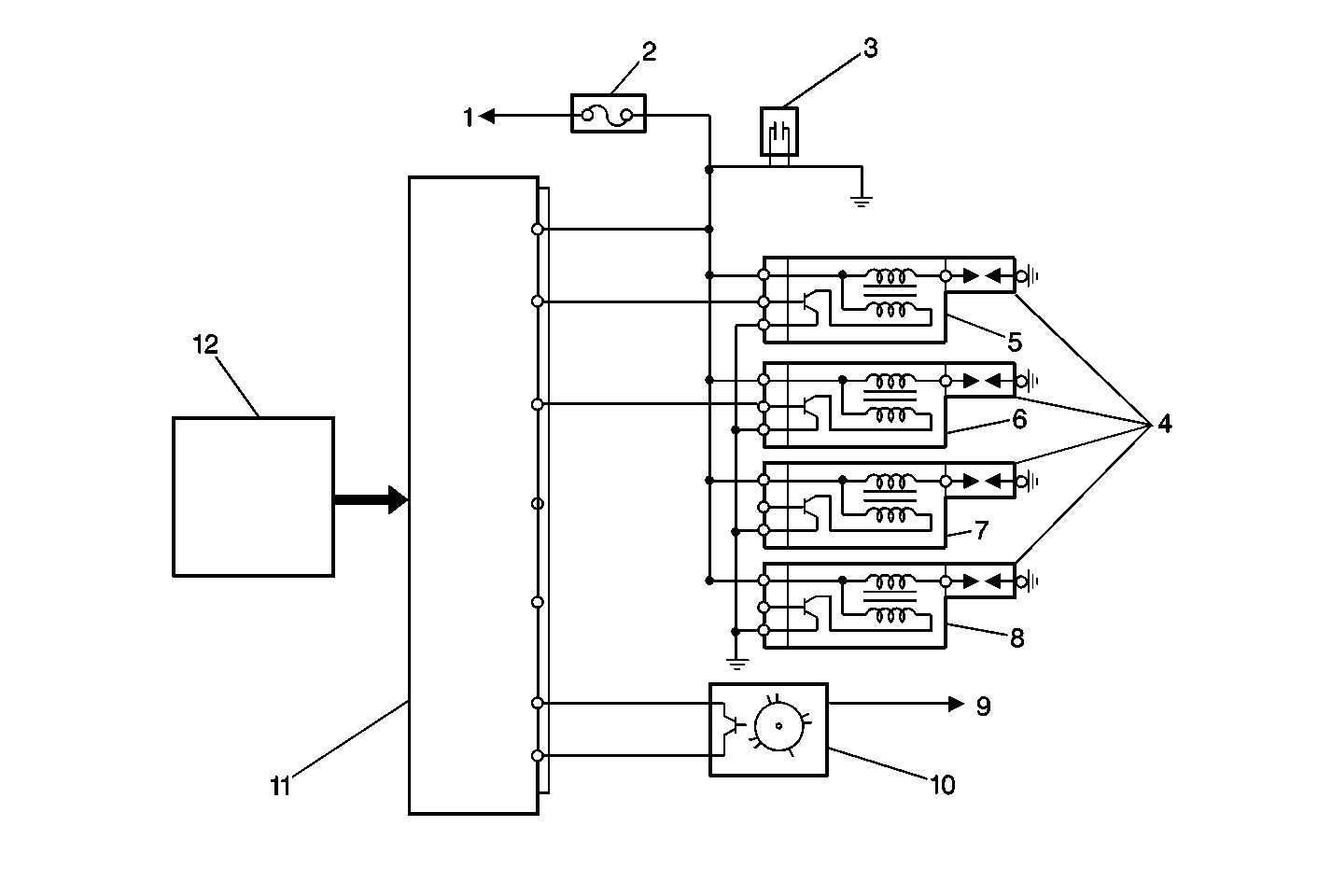
Object Number: 468069  Size: MF
(1)To Ignition Switch
(2)IG-COIL METER Fuse
(3)Noise Suppressor
(4)Spark Plugs
(5)Ignition Coil No.1
(6)Ignition Coil No.2
(7)Ignition Coil No.3
(8)Ignition Coil No.4
(9)From Main Relay
(10)CMP Sensor
(11)PCM
(12)Information and Sensor Inputs (to the PCM)

The electronic ignition system used in the 2.0L engine is a coil-on-plug design that is controlled by the powertrain control module (PCM).

The ignition system components cannot be disassembled or repaired. A component that is correctly diagnosed as faulty must be replaced as a complete unit.

Ignition Coil Assembly


Object Number: 419547  Size: SH

The ignition coil (2) has a high voltage output terminal and boot, that provides spark directly to the spark plug (3). Each ignition coil assembly has a built-in ignition module, or igniter, that controls the current flow in the primary coil winding. The secondary coil voltage travels directly to the spark plug, increasing secondary ignition voltage by eliminating the spark plug wire.
Operation

Ignition System


Object Number: 467906  Size: SH
(1)Ignition Coils
(2)Noise Suppressor
(3)PCM
(4)CMP Sensor
(5)Spark Plugs

The PCM uses reference pulses from the camshaft position (CMP) sensor in order to determine engine speed. The PCM cannot operate the ignition system -- or the fuel injectors -- without the engine speed signal from the CMP.

The four ignition coils supply spark to each engine cylinder, or spark plug, at precisely the right time. When the PCM sends a signal to the ignition module that is built into the ignition coil, the module responds by interrupting the current flow in the primary coil windings. Interrupting the current flow causes the electrical field around the primary coil to collapse, inducing a high voltage in the secondary coil. The secondary coil voltage travels unhindered to the spark plug, through the high voltage output terminal and boot assembly.

The PCM also uses the CMP sensor signal as an input for control of the fuel injectors and ignition timing. The crankshaft position (CKP) sensor signal is used by the PCM for engine misfire detection.

The PCM provides three modes of ignition timing control. Each ignition timing mode provides the most suitable spark advance for optimal engine performance. The following are the 3 modes of ignition timing control:

    • Initial timing control -- The initial timing control ignition advance provides better starting performance of the engine at start-up, when engine speed is less than 500 RPM. The PCM sets initial ignition timing advance to 5 degrees befor top dead center (BTDC).
    • Basic timing control -- After the engine is running, ignition timing advance is determined by combining basic timing control and compensating timing control. Basic timing control ignition advance is based on engine coolant temperature, engine speed, and intake air volume. The ignition timing advance value, calculated from the engine coolant temperature (ECT) sensor, the CMP sensor, and the mass air flow (MAF) sensor input, is added to the 5 degrees initial advance, and modified by the compensating timing control value.
    • Compensating timing control -- The compensating timing control ignition advance is added to the basic timing control value and varies according to engine and vehicle conditions. The most important factors in calculating the compensating ignition advance value are engine coolant temperature, intake air temperature, and engine idling demands.

Ignition timing on the 2.0L engine is adjustable. The CMP sensor housing can be repositioned, much like a distributor, in order to adjust the base ignition timing setting. A scan tool must be used to request that the PCM operate the ignition system in the ignition timing check mode. Refer to Ignition Timing Adjustment .

Noteworthy Ignition Information

Consider the following important information when servicing the ignition system:

    • The ignition coil secondary output voltage is very high -- more than 40,000 volts. Avoid body contact with the ignition high voltage secondary components when the engine is running or personal injury may result.
    • All four ignition coils are the same. Swapping ignition coils from one cylinder to another in order to determine the cause of a cylinder specific concern, can be a useful diagnostic procedure.
    • Be careful not to damage the secondary ignition terminal or boot when servicing the ignition system. Do not disassemble the ignition coil assembly for testing purposes.
    • Do not use a conventional tachometer in order to check engine speed on this ignition system. An inductive type pick-up can not be adapted to provide reliable engine speed information. Use a scan tool in order to monitor engine speed (RPM).