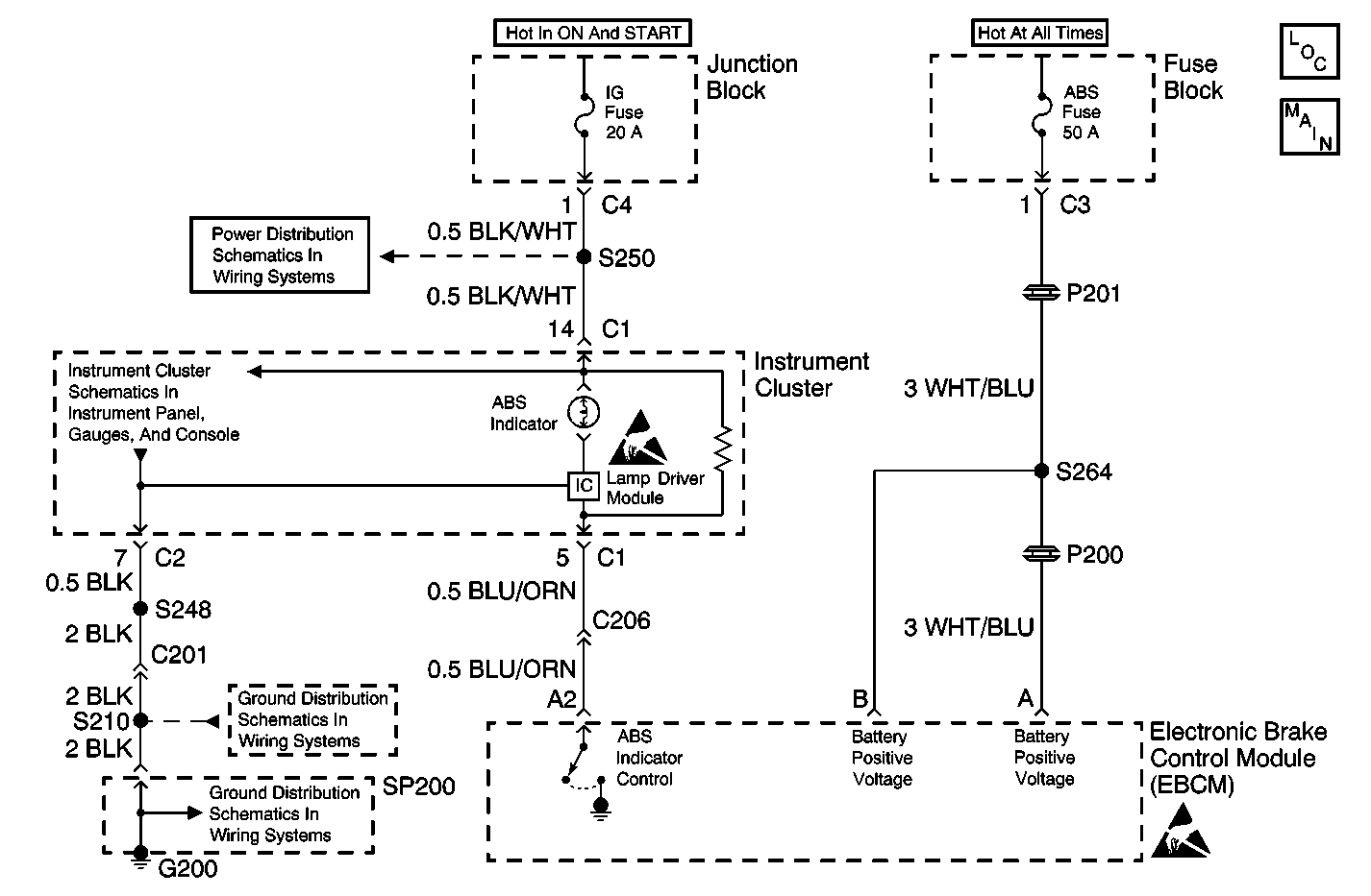
Circuit Description
The Electronic Brake Control Module (EBCM) controls the operation of the amber ABS indicator lamp by means of a lamp driver module.
When the ignition switch is turned to the ON position, the EBCM turns ON the ABS indicator for 3 seconds for a bulb check. Whenever a malfunction is detected within the ABS system, the EBCM tuns ON the ABS indicator, notifying the driver that ABS needs to be serviced.
Diagnostic Aids
Thoroughly inspect any circuitry that may cause the intermittent complaint for the following conditions:
| • | Backed out terminals |
| • | Improper mating |
| • | Broken locks |
| • | Improperly formed or damaged terminals |
| • | Poor terminal-to-wiring connections |
| • | Physical damage to the wiring harness |
| • | Short to ground between the lamp driver module and the amber ABS indicator lamp |
| • | Open circuit or high resistance between the EBCM and the lamp driver module |
| • | Malfunctioning lamp driver module |
Test Description
The number(s) below refer to the step number(s) on the diagnostic table.
-
The Diagnostic System Check must be the starting point for any ABS related diagnosis.
-
After repairs that set a certain DTCs (refer to Diagnostic Aids for specific DTCs) even after clearing DTCs the ABS will keep the ABS indicator ON until a road test is performed to confirm proper system operation.
-
Determines whether there is a short to ground in the ABS indicator circuit or a malfunctioning EBCM.
-
Refer to Diagnostic Aids for a list of DTCs that need road test confirmation before the ABS indicator is turned OFF.
-
A short to ground in the ABS Indicator Control circuit will keep the ABS indicator ON.
Step | Action | Value(s) | Yes | No |
|---|---|---|---|---|
1 | Was the Diagnostic System Check performed? | -- | Go to Step 2 | |
Is the ABS indicator ON? | -- | Go to Step 3 | Go to Step 4 | |
Is the ABS indicator ON? | -- | Go to Step 5 | Go to Step 6 | |
The malfunction that caused the EBCM to turn ON the ABS indicator is no longer present. Refer to Diagnostic Aids for additional information. Is the action complete? | -- | -- | ||
Repair the short to ground in the ABS Indicator Control circuit. Refer to Wiring Repairs in Wiring Systems. Is the repair complete? | -- | -- | ||
6 | Replace the EBCM. Refer to Electronic Brake Control Module Replacement . Is the repair complete? | -- | -- |
