|
| ||||||||||||
|---|---|---|---|---|---|---|---|---|---|---|---|---|---|
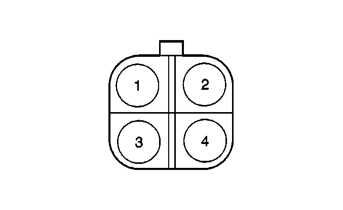
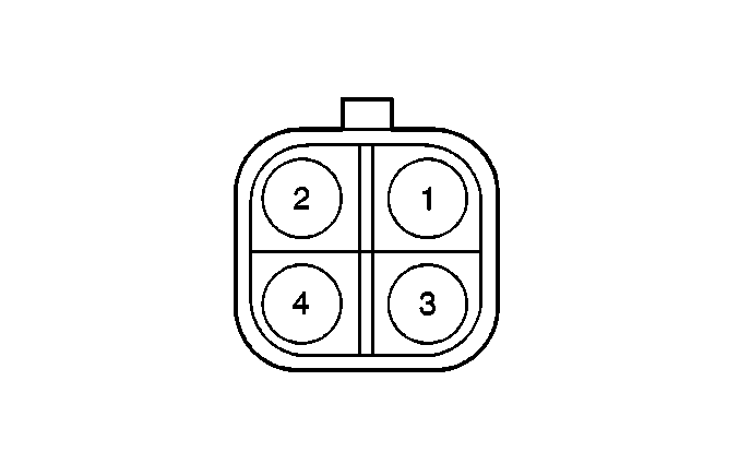
Connector Part Information |
| Connector Part Information |
| ||||||||||
Pin | Wire Color | Function | Pin | Wire Color | Function | ||||||||
1 | YEL/GRN | A/C Compressor Relay Supply Voltage | 1 | YEL/GRN | A/C Compressor Relay Supply Voltage | ||||||||
2 | PNK | A/C Compressor Relay Control | 2 | PNK | A/C Compressor Relay Control | ||||||||
3 | ORN | A/C Refrigerant Pressure Signal | 3 | ORN | A/C Refrigerant Pressure Signal | ||||||||
4 | YEL/BLU | A/C Condensor Fan Relay Control | 4 | YEL/BLU | A/C Condensor Fan Relay Control | ||||||||
|
| ||||||||||||
|---|---|---|---|---|---|---|---|---|---|---|---|---|---|
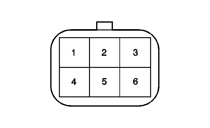
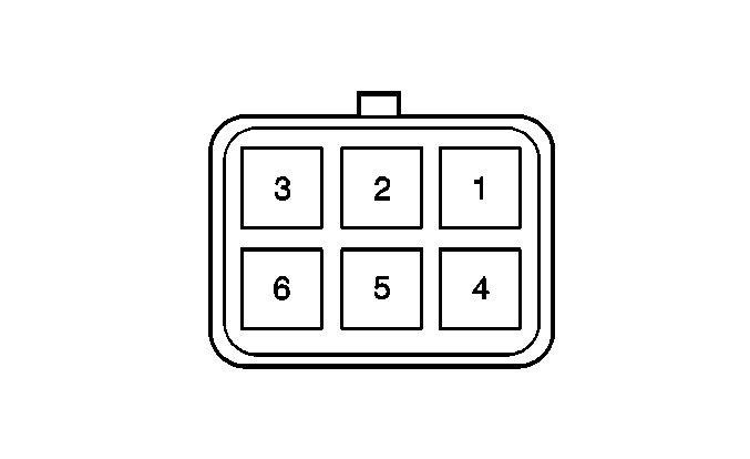
Connector Part Information |
| Connector Part Information |
| ||||||||||
Pin | Wire Color | Function | Pin | Wire Color | Function | ||||||||
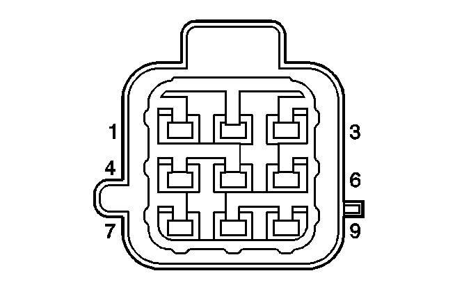
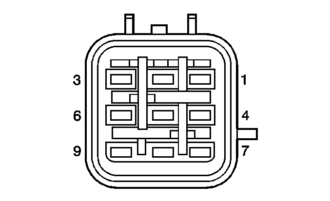
1 | PNK | Fuel Injector 1 Control | 1 | PNK | Fuel Injector 1 Control | ||||||||
2 | PNK/BLK | Fuel Injector 2 Control | 2 | PNK/BLK | Fuel Injector 2 Control | ||||||||
3 | PNK/GRN | Fuel Injector 3 Control | 3 | PNK/GRN | Fuel Injector 3 Control | ||||||||
4 | PNK/BLU | Fuel Injector 4 Control | 4 | PNK/BLU | Fuel Injector 4 Control | ||||||||
5 | BLU/BLK | Fuel Injector Voltage Feed | 5 | BLU/BLK | Fuel Injector Voltage Feed | ||||||||
6 | -- | Not Used | 6 | -- | Not Used | ||||||||
|
| ||||||||||||
|---|---|---|---|---|---|---|---|---|---|---|---|---|---|
Connector Part Information |
| Connector Part Information |
| ||||||||||
Pin | Wire Color | Function | Pin | Wire Color | Function | ||||||||
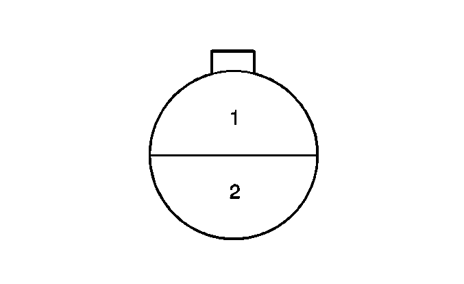
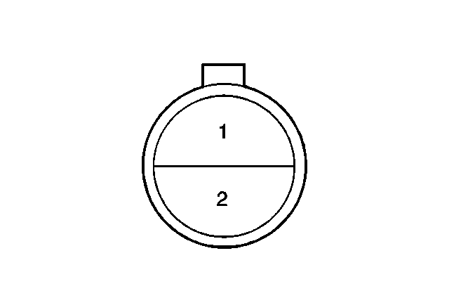
1 | GRY | Fuel Injector 1 | 1 | PNK | Fuel Injector 1 Control | ||||||||
2 | GRY/BLK | Fuel Injector 2 | 2 | PNK/BLK | Fuel Injector 2 Control | ||||||||
3 | GRY/WHT | Fuel Injector 3 | 3 | PNK/GRN | Fuel Injector 3 Control | ||||||||
4 | GRY/YEL | Fuel Injector 4 | 4 | PNK/BLU | Fuel Injector 4 Control | ||||||||
5 | GRY/GRN | Fuel Injector 5 | 5 | GRY/GRN | Fuel Injector 5 Control | ||||||||
6 | GRY/RED | Fuel Injector 6 | 6 | GRY/BLK | Fuel Injector 6 Control | ||||||||
7 | BLU/BLK | Fuel Injectors | 7 | BLU/BLK | Fuel Injector Voltage Feed | ||||||||
8--9 | -- | Not Used | 8--9 | -- | Not Used | ||||||||
|
| ||||||||||||
|---|---|---|---|---|---|---|---|---|---|---|---|---|---|
Connector Part Information |
| Connector Part Information |
| ||||||||||
Pin | Wire Color | Function | Pin | Wire Color | Function | ||||||||
1 | RED | A/C FUSE Supply Voltage | 1 | RED | A/C FUSE Supply Voltage | ||||||||
2 | -- | Not Used | 2 | -- | Not Used | ||||||||
|
| ||||||||||||
|---|---|---|---|---|---|---|---|---|---|---|---|---|---|
Connector Part Information |
| Connector Part Information |
| ||||||||||
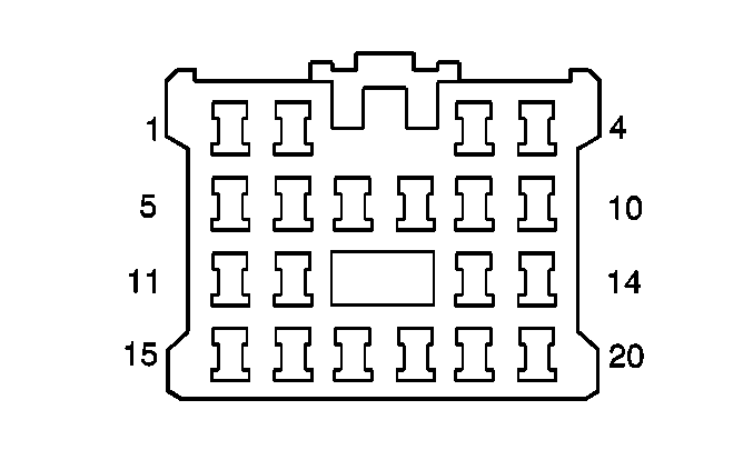
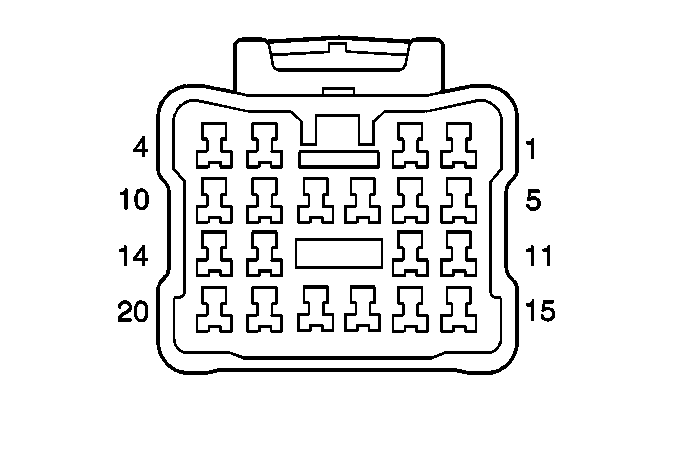
Pin | Wire Color | Function | Pin | Wire Color | Function | ||||||||
1 | BLK/ORN | Keyless Control | 1 | BLK/ORN | Keyless Control | ||||||||
2 | BLU | Door Lock Relay | 2 | BLU | Door Lock Relay | ||||||||
3 | BLU/RED | Driver Door Unlock Control | 3 | BLU/RED | Driver Door Unlock Control | ||||||||
4 | BLK/RED | Keyless Control | 4 | BLK/RED | Keyless Control | ||||||||
5 | BLK | Door Lock Relay | 5 | BLK | Door Lock Relay | ||||||||
6 | BLK | Door Unlock Relay | 6 | BLK | Door Unlock Relay | ||||||||
7 | BLK | Ground | 7 | BLK | Ground | ||||||||
8 | RED/WHT | Battery Positive Voltage | 8 | RED/WHT | Battery Positive Voltage | ||||||||
9 | RED/WHT | Battery Positive Voltage | 9 | RED/WHT | Battery Positive Voltage | ||||||||
10 | RED/WHT | Door Lock Relay | 10 | RED/WHT | Door Lock Relay | ||||||||
11 | PNK/GRN | Unlock Control | 11 | PNK/GRN | Unlock Control | ||||||||
12 | PNK | Lock Control | 12 | PNK | Lock Control | ||||||||
13 | BLU/RED | Door Unlock Relay | 13 | BLU/RED | Door Unlock Relay | ||||||||
14 | RED/WHT | Door Unlock Relay | 14 | RED/WHT | Door Unlock Relay | ||||||||
15 | BLK | Door Lock Relay | 15 | BLK | Door Lock Relay | ||||||||
16 | BLK | Door Unlock Relay | 16 | BLK | Door Unlock Relay | ||||||||
17 | PNK/WHT | Programming | 17 | PNK/WHT | Programming | ||||||||
18 | BLK/WHT | Ignition Positive Voltage | 18 | BLK/WHT | Ignition Positive Voltage | ||||||||
19 | PNK/GRN | Door Unlock Relay | 19 | PNK/GRN | Door Unlock Relay | ||||||||
20 | PNK | Door Lock Relay | 20 | PNK | Door Lock Relay | ||||||||

|

| ||||||||||||
|---|---|---|---|---|---|---|---|---|---|---|---|---|---|
Connector Part Information |
| Connector Part Information |
| ||||||||||
Pin | Wire Color | Function | Pin | Wire Color | Function | ||||||||
1-2 | -- | Not Used | 1-2 | -- | Not Used | ||||||||
3 | ORN/WHT | DRL Indicator Control | 3 | ORN/WHT | DRL Indicator Control | ||||||||
4 | -- | Not Used | 4 | -- | Not Used | ||||||||
5-6 | -- | Not Used | 5-6 | -- | Not Used | ||||||||
7 | RED/BLU | Not Used | 7 | RED/BLU | Not Used | ||||||||
8 | PPL | Brake Indicator Control | 8 | PPL | Brake Indicator Control | ||||||||
9 | PPL/GRN | Serial Data (PCM) | 9 | PPL/GRN | Serial Data (PCM) | ||||||||
10 | BLK/RED | Ignition Positive Voltage | 10 | BLK/RED | Ignition Positive Voltage | ||||||||
11-13 | -- | Not Used | 11-13 | -- | Not Used | ||||||||
14 | RED/GRN | Shift Indicator Lamp | 14 | RED/GRN | Shift Indicator Lamp | ||||||||
15 | GRY/BLU | POWER Indicator Control | 15 | GRY/BLU | POWER Indicator Control | ||||||||
16 | WHT/BLK | OD/OFF Indicator Control | 16 | WHT/BLK | OD/OFF Indicator Control | ||||||||
17 | BLU/WHT | Fuel Level Input | 17 | BLU/WHT | Fuel Level Input | ||||||||
18 | BLK | Ground-G200 | 18 | BLK | Ground-G200 | ||||||||
19 | PNK/BLU | Shift Indicator | 19 | PNK/BLU | Shift Indicator | ||||||||
20 | GRN/BLK | Request Signal | 20 | GRN/BLK | Request Signal | ||||||||
|
| ||||||||||||
|---|---|---|---|---|---|---|---|---|---|---|---|---|---|
Connector Part Information |
| Connector Part Information |
| ||||||||||
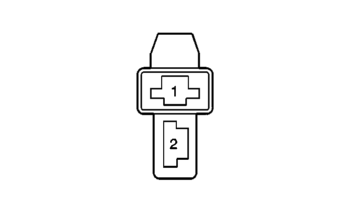
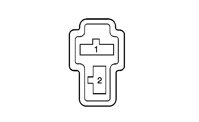
Pin | Wire Color | Function | Pin | Wire Color | Function | ||||||||
1 | PNK | Blower Control High | 1 | PNK | Blower Control High | ||||||||
2 | BLK | Ground-G200 | 2 | BLK | Ground-G200 | ||||||||
|
| ||||||||||||
|---|---|---|---|---|---|---|---|---|---|---|---|---|---|
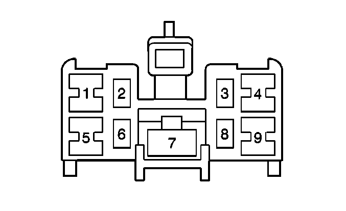
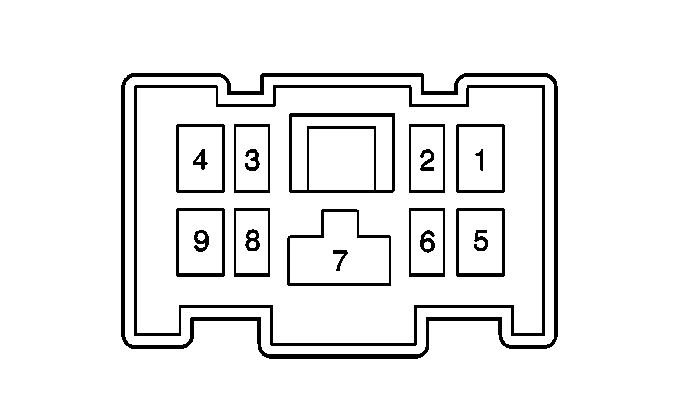
Connector Part Information |
| Connector Part Information |
| ||||||||||
Pin | Wire Color | Function | Pin | Wire Color | Function | ||||||||
1 | YEL/BLK | Ignition Positive Voltage-ON | 1 | YEL/BLK | Ignition Positive Voltage-ON | ||||||||
2 | BLK | Ground-G200,G201 | 2 | BLK | Ground-G200,G201 | ||||||||
3 | GRN | Ignition Key-In Signal | 3 | BLU/RED | Ignition Key-In Signal | ||||||||
4 | BLK/WHT | Ignition Positive Voltage-ON/OFF | 4 | BLK/BLU | Ignition Positive Voltage-ON/OFF | ||||||||
5 | BLK/YEL | Ignition Positive Voltage-Start | 5 | BLK/RED | Ignition Positive Voltage-Start | ||||||||
6 | BLK | Brake Indicator Control | 6 | PPL/RED | Brake Indicator Control | ||||||||
7 | WHT/YEL | Battery Positive Voltage | 7 | WHT/GRN | Battery Positive Voltage | ||||||||
8 | GRN | Battery Positive Voltage | 8 | WHT | Battery Positive Voltage | ||||||||
9 | BLU | Ignition Positive Voltage-ACC/ON | 9 | BLU | Ignition Positive Voltage-ACC/ON | ||||||||
|
| ||||||||||||
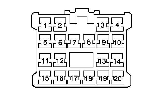
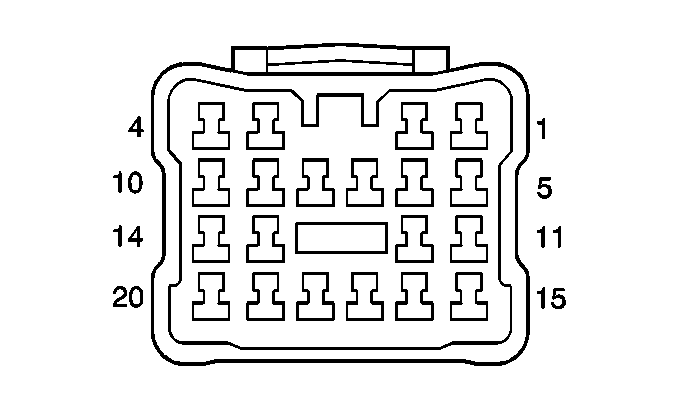
|---|---|---|---|---|---|---|---|---|---|---|---|---|---|
Connector Part Information |
| Connector Part Information |
| ||||||||||
Pin | Wire Color | Function | Pin | Wire Color | Function | ||||||||
1 | BLK/YEL | Ground-G103 | 1 | BLK/YEL | Ground-G103 | ||||||||
2 | GRN | Battery Positive Voltage | 2 | GRN | Battery Positive Voltage | ||||||||
3 | BLU/RED | Not Used | 3 | BLU/RED | Not Used | ||||||||
4 | BLU | Battery Positive Voltage | 4 | BLU | Battery Positive Voltage | ||||||||
5 | GRY/YEL | Sensor Ground | 5 | GRY/YEL | Sensor Ground | ||||||||
6 | RED/GRN | HO2S2 Signal | 6 | RED/GRN | HO2S2 Signal | ||||||||
7 | BLU/RED | Door Unlock Signal | 7 | BLU/RED | Door Unlock Signal | ||||||||
8 | BLU | Door Lock Signal | 8 | BLU | Door Lock Signal | ||||||||
9 | RED/YEL | Left Rear Window Down Signal | 9 | RED/YEL | Left Rear Window Down Signal | ||||||||
10 | RED/WHT | Right Rear Window Down Signal | 10 | RED/WHT | Right Rear Window Down Signal | ||||||||
11 | BARE | Shield Wire | 11 | BARE | Shield Wire | ||||||||
12 | PNK/GRN | HO2S2 Heater Control | 12 | PNK/GRN | HO2S2 Heater Control | ||||||||
13 | GRN/YEL | Left Rear Window Up Signal | 13 | GRN/YEL | Left Rear Window Up Signal | ||||||||
14 | GRN/WHT | Right Rear Window Up Signal | 14 | GRN/WHT | Right Rear Window Up Signal | ||||||||
15 | GRY/YEL | Sensor Ground | 15 | GRY/YEL | Sensor Ground | ||||||||
16 | BRN/RED | Reference Voltage | 16 | BRN/RED | Reference Voltage | ||||||||
17 | GRY/RED | Fuel Tank Pressure Input | 17 | GRY/RED | Fuel Tank Pressure Input | ||||||||
18 | -- | Not Used | 18 | -- | Not Used | ||||||||
19 | BLU/WHT | Ignition Positive Voltage | 19 | BLU/WHT | Ignition Positive Voltage | ||||||||
20 | RED/WHT | Battery Positive Voltage | 20 | RED/WHT | Battery Positive Voltage | ||||||||

|

| ||||||||||||
|---|---|---|---|---|---|---|---|---|---|---|---|---|---|
Connector Part Information |
| Connector Part Information |
| ||||||||||
Pin | Wire Color | Function | Pin | Wire Color | Function | ||||||||
1 | YEL | RR Wheel Speed Sensor Signal High | 1 | YEL | RR Wheel Speed Sensor Signal High | ||||||||
2 | YEL/BLK | RR Wheel Speed Sensor Signal Low | 2 | YEL/BLK | RR Wheel Speed Sensor Signal Low | ||||||||
3 | RED | Back-Up Lamp Signal | 3 | RED | Back-Up Lamp Signal | ||||||||
4 | RED/BLK | Not Used | 4 | RED/BLK | Not Used | ||||||||
5 | LT GRN | LR Wheel Speed Sensor Signal High | 5 | LT GRN | LR Wheel Speed Sensor Signal High | ||||||||
6 | LT GRN/BLK | LR Wheel Speed Sensor Signal Low | 6 | LT GRN/BLK | LR Wheel Speed Sensor Signal Low | ||||||||
7-8 | -- | Not Used | 7-8 | -- | Not Used | ||||||||
9 | DK GRN/WHT | Battery Positive Voltage | 9 | DK GRN/WHT | Battery Positive Voltage | ||||||||
10 | RED/BLU | Not Used | 10 | RED/BLU | Not Used | ||||||||
11 | -- | Not Used | 11 | -- | Not Used | ||||||||
12 | WHT | Battery Positive Voltage | 12 | WHT | Battery Positive Voltage | ||||||||
13 | BLK/RED | Dome Lamp Signal | 13 | BLK/RED | Dome Lamp Signal | ||||||||
14 | DK GRN/RED | Not Used | 14 | DK GRN/RED | Not Used | ||||||||
15 | RED/BLU | Battery Positive Voltage | 15 | RED/BLU | Battery Positive voltage | ||||||||
16 | -- | Not Used | 16 | -- | Not Used | ||||||||
17 | PNK | Lock Control | 17 | PNK | Lock Control | ||||||||
18 | PNK/GRN | Not Used | 18 | PNK/GRN | Not Used | ||||||||
19 | PNK/BLK | Fuel Pump Relay Output | 19 | PNK/BLK | Fuel Pump Relay Output | ||||||||
20 | DK GRN/ORN | Not Used | 20 | DK GRN/ORN | Not Used | ||||||||
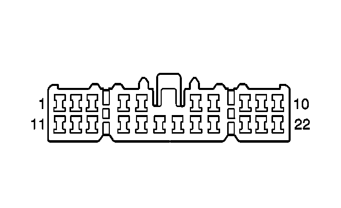
|
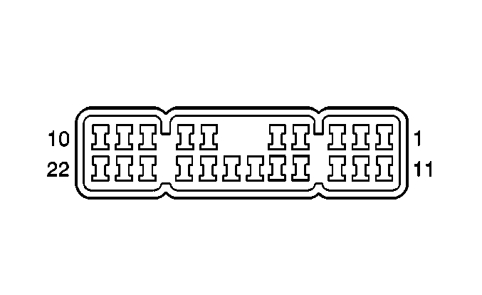
| ||||||||||||
|---|---|---|---|---|---|---|---|---|---|---|---|---|---|
Connector Part Information |
| Connector Part Information |
| ||||||||||
Pin | Wire Color | Function | Pin | Wire Color | Function | ||||||||
1 | BLU/ORN | ABS Indicator Control | 1 | BLU/ORN | ABS Indicator Control | ||||||||
2 | PPL/RED | Not Used | 2 | PPL/RED | Not Used | ||||||||
3 | RED/BLK | Brake Indicator | 3 | RED/BLK | Brake Indicator | ||||||||
4 | ORN/BLK | 4WD Indicator Control | 4 | ORN/BLK | 4WD Indicator Control | ||||||||
5 | YEL/BLK | Oil Pressure Indicator | 5 | YEL/BLK | Oil Pressure Indicator | ||||||||
6 | PNK/WHT | Programming Signal | 6 | PNK/WHT | Programming Signal | ||||||||
7 | ORN/BLU | Right Front Speaker (-) | 7 | ORN/BLU | Right Front Speaker (-) | ||||||||
8 | ORN | Right Front Speaker (+) | 8 | ORN | Right Front Speaker (+) | ||||||||
9 | BRN/WHT | Left Front Speaker (-) | 9 | BRN/WHT | Left Front Speaker (-) | ||||||||
10 | BRN/BLK | Left Front Speaker (+) | 10 | BRN/BLK | Left Front Speaker (+) | ||||||||
11 | PNK/WHT | Blower On Signal | 11 | PNK/WHT | Blower On Signal | ||||||||
12 | PNK/BLK | Blower Control Low | 12 | PNK/BLK | Blower Control Low | ||||||||
13 | PNK/BLU | Blower Control M1 | 13 | PNK/BLU | Blower Control M1 | ||||||||
14 | PNK/DK GRN | Blower Control M2 | 14 | PNK/DK GRN | Blower Control M2 | ||||||||
15 | -- | Not Used | 15 | WHT/BLK | Not Used | ||||||||
16 | BLU/RED | Ignition Key-In Signal | 16 | BLU/RED | Ignition Key-In Signal | ||||||||
17 | BLK/DK GRN | Serial Data | 17 | BLK/DK GRN | Serial Data | ||||||||
18 | PPL/WHT | Serial Data (EBCM) | 18 | PPL/WHT | Serial Data (EBCM) | ||||||||
19 | LT GRN | Mode Signal | 19 | LT GRN | Mode Signal | ||||||||
20 | LT GRN/WHT | Indicator Control | 20 | LT GRN/WHT | Indicator Control | ||||||||
21 | GRY/YEL | Cruise Indicator Control | 21 | GRY/YEL | Cruise Indicator Control | ||||||||
22 | PPL/YEL | MIL Control | 22 | PPL/YEL | MIL Control | ||||||||
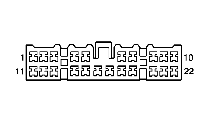
|
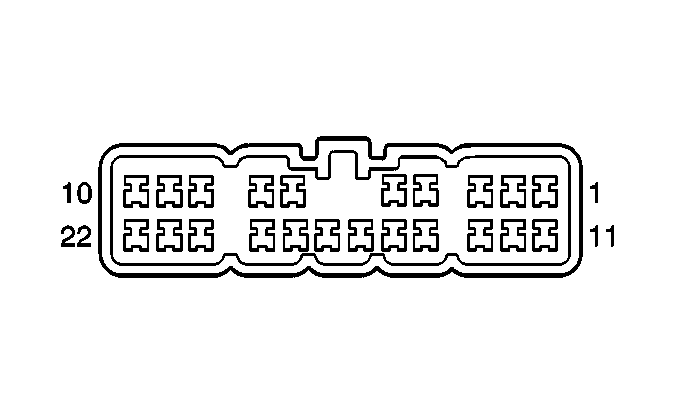
| ||||||||||||
|---|---|---|---|---|---|---|---|---|---|---|---|---|---|
Connector Part Information |
| Connector Part Information |
| ||||||||||
Pin | Wire Color | Function | Pin | Wire Color | Function | ||||||||
1 | -- | Not Used | 1 | -- | Not Used | ||||||||
2 | WHT | Battery Positive Voltage | 2 | WHT | Battery Positive Voltage | ||||||||
3 | RED/GRN | Not Used | 3 | RED/GRN | Not Used | ||||||||
4 | DK GRN | Hazard Signal | 4 | DK GRN | Hazard Signal | ||||||||
5 | YEL | Ignition Positive Voltage | 5 | YEL | Ignition Positive Voltage | ||||||||
6 | RED/YEL | Lights On Signal | 6 | RED/YEL | Lights On Signal | ||||||||
7 | RED | HI Beam Indicator | 7 | RED | HI Beam Indicator | ||||||||
8 | WHT/BLU | Battery Positive Voltage | 8 | WHT/BLU | Battery Positive Voltage | ||||||||
9 | WHT/RED | Charge Indicator | 9 | WHT/RED | Charge Indicator | ||||||||
10 | -- | Not Used | 10 | -- | Not Used | ||||||||
11 | BLU/YEL | VSS Input | 11 | BLU/YEL | VSS Input | ||||||||
12 | BLK/YEL | Ground-G103 | 12 | BLK/YEL | Ground-G103 | ||||||||
13 | YEL/WHT | ECT Sensor Input | 13 | YEL/WHT | ECT Sensor Input | ||||||||
14 | BRN | Engine Speed Output | 14 | BRN | Engine speed Output | ||||||||
15 | DK GRN/WHT | RT Outside Mirror Motor LFT/RT Control | 15 | DK GRN/WHT | RT Outside Mirror Motor LFT/RT Control | ||||||||
16 | LT GRN/BLK | LFT Outside Mirror Motor LFT/RT Control | 16 | LT GRN/BLK | LFT Outside Mirror Motor LFT/RT Control | ||||||||
17 | BRN/RED | RT Outside Mirror Motor Up/Down Control | 17 | BRN/RED | RT Outside Mirror Motor Up/Down Control | ||||||||
18 | BRN/YEL | LFT Outside Mirror Motor Up/Down Control | 18 | BRN/YEL | LFT Outside Mirror Motor Up/Down Control | ||||||||
19 | GRY | Switch Control | 19 | GRY | Switch Control | ||||||||
20 | BLK/RED | Idle-Up Signal | 20 | BLK/RED | Idle-Up Signal | ||||||||
21 | -- | Not Used | 21 | -- | Not Used | ||||||||
22 | YEL/DK GRN | Ignition Positive Voltage | 22 | YEL/DK GRN | Ignition Positive Voltage | ||||||||
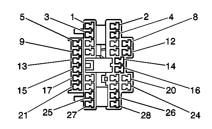
|
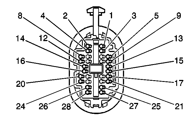
| ||||||||||||
|---|---|---|---|---|---|---|---|---|---|---|---|---|---|
Connector Part Information |
| Connector Part Information |
| ||||||||||
Pin | Wire Color | Function | Pin | Wire Color | Function | ||||||||
1 | -- | Not Used | 1 | -- | Not Used | ||||||||
2 | BRN/BLK | Left Front Speaker Positive | 2 | BRN/BLK | Left Front Speaker Positive | ||||||||
3 | -- | Not Used | 3 | -- | Not Used | ||||||||
4 | BRN/WHT | Left Front Speaker Negative | 4 | BRN/WHT | Left Front Speaker Negative | ||||||||
5 | BLU/WHT | Master Switch Battery Positive Voltage | 5 | BLU/WHT | Master Switch Battery Positive Voltage | ||||||||
6 | -- | Not Used | 6 | -- | Not Used | ||||||||
7 | GRY | Power Mirror Motor Feed Circuit | 7 | GRY | Power Mirror Motor Feed Circuit | ||||||||
8 | -- | Not Used | 8 | -- | Not Used | ||||||||
9 | DK GRN/BLK | Right Front Power Window Up Feed Circuit | 9 | DK GRN/BLK | Right Front Power Window Up Feed Circuit | ||||||||
10 | LT GRN/BLU | Left Power Mirror Left/Right Control Ground Circuit | 10 | LT GRN/BLU | Left Power Mirror Left/Right Control Ground Circuit | ||||||||
11 | BRN/YEL | Left Power Mirror Up/Down Control Ground Circuit | 11 | BRN/YEL | Left Power Mirror Up/Down Control Ground Circuit | ||||||||
12 | -- | Not Used | 12 | -- | Not Used | ||||||||
13 | RED/BLK | Right Front Window Switch Down Feed | 13 | RED/BLK | Right Front Window Switch Down Feed | ||||||||
14 | BLU | Door Lock Motor Voltage Feed | 14 | BLU | Door Lock Motor Voltage Feed | ||||||||
15 | DK GRN/WHT | Right Rear Window Switch Up Feed | 15 | DK GRN/WHT | Right Rear Window Switch Up Feed | ||||||||
16 | BLU/RED | Door Unlock Motor Voltage Feed | 16 | BLU/RED | Door Unlock Motor Voltage Feed | ||||||||
17 | DK GRN/YEL | Left Rear Window Switch Up Feed | 17 | DK GRN/YEL | Left Rear Window Switch Up Feed | ||||||||
18-19 | -- | Not Used | 18-19 | -- | Not Used | ||||||||
20 | PNK | Remote Control Door Lock Reciever Lock Control | 20 | PNK | Remote Control Door Lock Reciever Lock Control | ||||||||
21 | RED/YEL | Left Rear Window Switch Down Feed | 21 | RED/YEL | Left Rear Window Switch Down Feed | ||||||||
22-23 | -- | Not Used | 22-23 | -- | Not Used | ||||||||
24 | PNK/DK GRN | Remote Control Door Lock Reciever Unlock Control | 24 | PNK/DK GRN | Remote Control Door Lock Reciever Unlock Control | ||||||||
25 | RED/WHT | Right Rear Window Switch Down Feed | 25 | RED/WHT | Right Rear Window Switch Down Feed | ||||||||
26-27 | -- | Not Used | 26-27 | -- | Not Used | ||||||||
28 | BLK | Ground-G200 | 28 | BLK | Ground-G200 | ||||||||
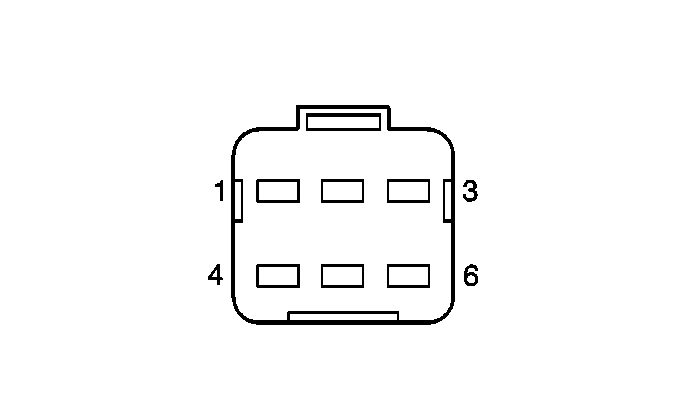
|
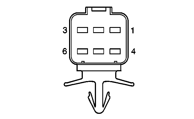
| ||||||||||||
|---|---|---|---|---|---|---|---|---|---|---|---|---|---|
Connector Part Information |
| Connector Part Information |
| ||||||||||
Pin | Wire Color | Function | Pin | Wire Color | Function | ||||||||
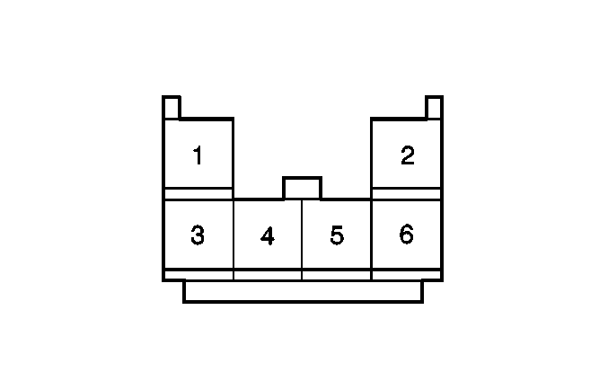
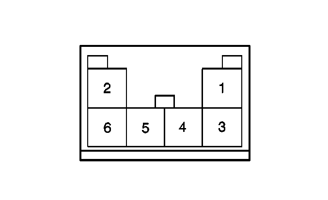
1 | -- | Not Used | 1 | -- | Not Used | ||||||||
2 | WHT | Battery Positive Voltage | 2 | WHT | Battery Positive Voltage | ||||||||
3 | BLK/RED | Door Lock Signal | 3 | BLK/RED | Door Lock Signal | ||||||||
4 | BLK | Ground-G200 | 4 | BLK | Ground-G200 | ||||||||
5-6 | BARE | Not Used | 5-6 | BARE | Not Used | ||||||||
|
| ||||||||||||
|---|---|---|---|---|---|---|---|---|---|---|---|---|---|
Connector Part Information |
| Connector Part Information |
| ||||||||||
Pin | Wire Color | Function | Pin | Wire Color | Function | ||||||||
1 | GRY/YEL | HO2S Sensor Ground | 1 | GRY/YEL | HO2S Sensor Ground | ||||||||
2 | RED/GRN | HO2S 5 volt reference signal | 2 | RED/GRN | HO2S 5 volt reference signal | ||||||||
3-4 | -- | Not Used | 3-4 | -- | Not Used | ||||||||
5 | -- | Shield | 5 | -- | Shield | ||||||||
6 | PNK/GRN | HO2S Heater Control | 6 | PNK/GRN | HO2S Heater Control | ||||||||

|

| ||||||||||||
|---|---|---|---|---|---|---|---|---|---|---|---|---|---|
Connector Part Information |
| Connector Part Information |
| ||||||||||
Pin | Wire Color | Function | Pin | Wire Color | Function | ||||||||
1 | -- | Not Used | 1 | -- | Not Used | ||||||||
2 | ORN | Right Front Speaker Positive | 2 | ORN | Right Front Speaker Positive | ||||||||
3 | -- | Not Used | 3 | -- | Not Used | ||||||||
4 | ORN/BLU | Right Front Speaker Negative | 4 | ORN/BLU | Right Front Speaker Negative | ||||||||
5 | BLU/WHT | Master Window Switch Battery Positive Voltage | 5 | BLU/WHT | Master Window Switch Battery Positive Voltage | ||||||||
6 | -- | Not Used | 6 | -- | Not Used | ||||||||
7 | GRY | Power Mirror Supply Voltage | 7 | GRY | Power Mirror Supply Voltage | ||||||||
8 | -- | Not Used | 8 | -- | Not Used | ||||||||
9 | GRN/BLK | Right Front Window Switch Up Voltage Feed. | 9 | GRN/BLK | Right Front Window Switch Up Voltage Feed. | ||||||||
10 | GRN/WHT | Right Power Mirror Left/Right Voltage Feed | 10 | GRN/WHT | Right Power Mirror Left/Right Voltage Feed | ||||||||
11 | BRN/RED | Right Power Mirror Up/Down Voltage Feed | 11 | BRN/RED | Right Power Mirror Up/Down Voltage Feed | ||||||||
12 | -- | Not Used | 12 | -- | Not Used | ||||||||
13 | RED/BLK | Right Front Window Switch Down Voltage Feed | 13 | RED/BLK | Right Front Window Switch Down Voltage Feed | ||||||||
14 | BLU | Door Lock Motor Supply Voltage | 14 | BLU | Door Lock Motor Supply Voltage | ||||||||
15 | -- | Not Used | 15 | -- | Not Used | ||||||||
16 | BLU/RED | Door Unlock Motor Supply Voltage | 16 | BLU/RED | Door Unlock Motor Supply Voltage | ||||||||
17-19 | -- | Not Used | 17-19 | -- | Not Used | ||||||||
20 | PNK | Remote Control Door Lock Reciever Lock Control | 20 | PNK | Remote Control Door Lock Reciever Lock Control | ||||||||
21-27 | -- | Not Used | 21-27 | -- | Not Used | ||||||||
28 | BLK | Ground-G201 | 28 | BLK | Ground-G201 | ||||||||
|
| ||||||||||||
|---|---|---|---|---|---|---|---|---|---|---|---|---|---|
Connector Part Information |
| Connector Part Information |
| ||||||||||
Pin | Wire Color | Function | Pin | Wire Color | Function | ||||||||
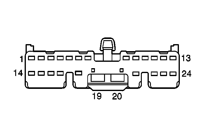
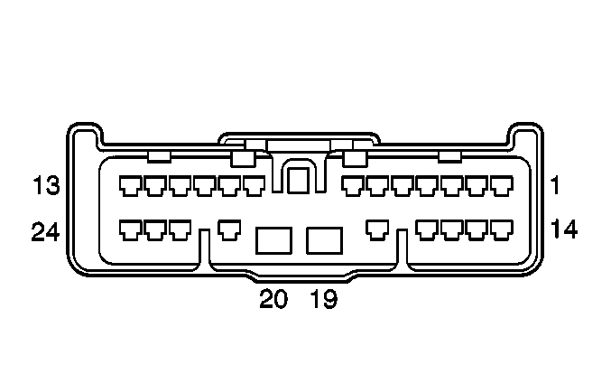
1 | YEL/WHT | ECT Gage | 1 | YEL/WHT | ECT Gage | ||||||||
2 | BLU/YEL | VSS Input | 2 | BLU/YEL | VSS Input | ||||||||
3 | ORN/GRN | Relay Control | 3 | ORN/GRN | Relay Control | ||||||||
4 | BLK/GRN | Shield Wire | 4 | -- | Shield Wire | ||||||||
5 | -- | Not Used | 5 | -- | Not Used | ||||||||
6 | RED | Axle Actuator Control | 6 | RED | Axle Actuator Control | ||||||||
7-8 | -- | Not Used | 7-8 | -- | Not Used | ||||||||
9 | GRY/YEL | Sensor Ground | 9 | GRY/YEL | Sensor Ground | ||||||||
10 | BLK | Ground-G201 | 10 | BLK | Ground-G201 | ||||||||
11 | BLU/BLK | Main Relay Output | 11 | BLU/BLK | Main Relay Output | ||||||||
12 | RED | Back-Up Lamp Signal | 12 | RED | Back-Up Lamp Signal | ||||||||
13-15 | -- | Not Used | 13-15 | -- | Not Used | ||||||||
16 | BLK/YEL | Ground-G103 | 16 | BLK/YEL | Ground-G103 | ||||||||
17 | YEL/BLK | Oil Pressure Indicator | 17 | YEL/BLK | Oil Pressure Indicator | ||||||||
18 | PNK | Axle Actuator Control | 18 | PNK | Axle Actuator Control | ||||||||
19 | BLK/YEL | Start Signal M/T | 19 | BLK/YEL | Start Signal M/T | ||||||||
20 | BLK/RED | Ignition Positive Voltage A/T | 20 | BLK/RED | Ignition Positive Voltage A/T | ||||||||
21 | BLK/GRN | DLC Ground | 21 | BLK/GRN | DLC Ground | ||||||||
22 | BLK/WHT | Ignition Positive Voltage | 22 | BLK/WHT | Ignition Positive Voltage | ||||||||
23 | YEL | Ignition Positive Voltage | 23 | YEL | Ignition Positive Voltage | ||||||||
24 | WHT/RED | Charge Indicator | 24 | WHT/RED | Charge Indicator | ||||||||
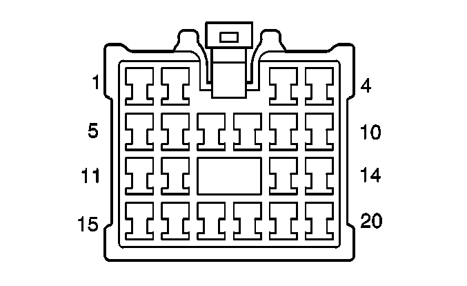
|
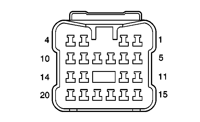
| ||||||||||||
|---|---|---|---|---|---|---|---|---|---|---|---|---|---|
Connector Part Information |
| Connector Part Information |
| ||||||||||
Pin | Wire Color | Function | Pin | Wire Color | Function | ||||||||
1 | DK GRN/BLU | Not Used | 1 | DK GRN/BLU | Not Used | ||||||||
2 | RED/YEL | Battery Positive Voltage | 2 | RED/YEL | Battery Positive Voltage | ||||||||
3 | BLU/WHT | Fuel Level Input | 3 | BLU/WHT | Fuel Level Input | ||||||||
4 | -- | Not Used | 4 | -- | Not Used | ||||||||
5 | ORN | Ignition Positive Voltage | 5 | ORN | Ignition Positive Voltage | ||||||||
6 | -- | Not Used | 6 | -- | Not Used | ||||||||
7 | LT GRN | Left Rear Speaker (+) | 7 | LT GRN | Left Rear Speaker (+) | ||||||||
8 | GRY | Right Rear Speaker (+) | 8 | GRY | Right Rear Speaker (+) | ||||||||
9 | GRY/RED | Seat Belt Indicator | 9 | GRY/RED | Seat Belt Indicator | ||||||||
10 | -- | Not Used | 10 | -- | Not Used | ||||||||
11 | BLK/BLU | Door Open Signal | 11 | BLK/BLU | Door Open Signal | ||||||||
12 | -- | Not Used | 12 | -- | Not Used | ||||||||
13 | BLK/RED | Not Used | 13 | BLK/RED | Not Used | ||||||||
14 | -- | Not Used | 14 | -- | Not Used | ||||||||
15 | BLU | Ignition Positive Voltage | 15 | BLU | Ignition Positive Voltage | ||||||||
16 | -- | Not Used | 16 | -- | Not Used | ||||||||
17 | LT GRN/BLK | Left Rear Speaker (-) | 17 | LT GRN/BLK | Left Rear Speaker (-) | ||||||||
18 | GRY/BLK | Right Rear Speaker (-) | 18 | GRY/BLK | Right Rear Speaker (-) | ||||||||
19 | BLK/RED | Relay Control | 19 | BLK/RED | Relay Control | ||||||||
20 | -- | Not Used | 20 | -- | Not Used | ||||||||
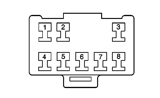
|
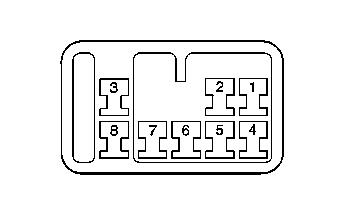
| ||||||||||||
|---|---|---|---|---|---|---|---|---|---|---|---|---|---|
Connector Part Information |
| Connector Part Information |
| ||||||||||
Pin | Wire Color | Function | Pin | Wire Color | Function | ||||||||
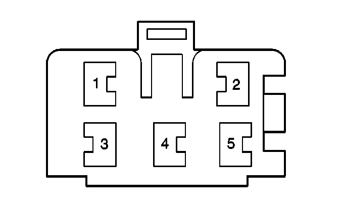
1 | PNK/WHT | Idle-UP Control | 1 | PNK/WHT | Idle-Up Control | ||||||||
2 | PNK | A/C Compressor Relay Control | 2 | PNK | A/C Compressor Relay Control | ||||||||
3 | GRN/BLK | Request Signal | 3 | GRN/WHT | Request Signal | ||||||||
4 | BLK/YEL | Ground-G103 | 4 | BLK | Ground-G103 | ||||||||
5 | YEL/BLK | A/C Idle-Up | 5 | YEL/BLK | A/C Idle-Up | ||||||||
6 | BLK/WHT | Ignition Positive Voltage | 6 | BLK/WHT | Ignition Positive Voltage | ||||||||
7 | GRY/WHT | A/C Cut-Out | 7 | GRN/YEL | A/C Cut-Out | ||||||||
8 | ORN | A/C Refrigerant Pressure Signal | 8 | ORN | A/C Refrigerant Pressure Signal | ||||||||
|

| ||||||||||||
|---|---|---|---|---|---|---|---|---|---|---|---|---|---|
Connector Part Information |
| Connector Part Information |
| ||||||||||
Pin | Wire Color | Function | Pin | Wire Color | Function | ||||||||
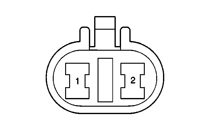
1 | YEL/GRN | Air Bag Warning Control | 1 | BLU | Air Bag Warning Control | ||||||||
2 | BLK | Ground-G200 | 2 | -- | Not Used | ||||||||
3 | -- | Not Used | 3 | -- | Not Used | ||||||||
4 | GRY/RED | Seat Belt Switch Signal | 4 | YEL/BLU | Seat Belt Switch Signal | ||||||||
5 | PPL/GRN | Serial Data | 5 | WHT/BLK | Serial Data | ||||||||
|
| ||||||||||||
|---|---|---|---|---|---|---|---|---|---|---|---|---|---|
Connector Part Information |
| Connector Part Information |
| ||||||||||
Pin | Wire Color | Function | Pin | Wire Color | Function | ||||||||
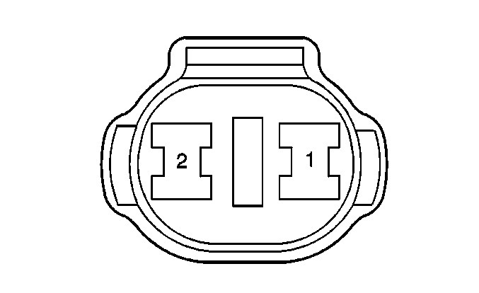
1 | BLU | Battery Positive Voltage | 1 | BLU | Battery Positive Voltage | ||||||||
2 | BLU/RED | Ground-G201 | 2 | BLU/RED | Ground-G201 | ||||||||

| |||||||||||||
|---|---|---|---|---|---|---|---|---|---|---|---|---|---|
Connector Part Information |
| Connector Part Information |
| ||||||||||
Pin | Wire Color | Function | Pin | Wire Color | Function | ||||||||
1 | BLU/WHT | Door Lock Switch Voltage Supply | 1 | BLU/WHT | Door Lock Switch Voltage Supply | ||||||||
2 | GRN/YEL | Left Rear Window Switch Up Feed | 2 | GRN/YEL | Left Rear Window Switch Up Feed | ||||||||
3 | RED/YEL | Left Rear Window Switch Down Feed | 3 | RED/YEL | Left Rear Window Switch Down Feed | ||||||||

|

| ||||||||||||
|---|---|---|---|---|---|---|---|---|---|---|---|---|---|
Connector Part Information |
| Connector Part Information |
| ||||||||||
Pin | Wire Color | Function | Pin | Wire Color | Function | ||||||||
1 | BLU | Battery Positive Voltage | 1 | BLU | Battery Positive Voltage | ||||||||
2 | BLU/RED | Ground-G201 | 2 | BLU/RED | Ground-G201 | ||||||||

| |||||||||||||
|---|---|---|---|---|---|---|---|---|---|---|---|---|---|
Connector Part Information |
| Connector Part Information |
| ||||||||||
Pin | Wire Color | Function | Pin | Wire Color | Function | ||||||||
1 | BLU/WHT | Door Lock Switch Voltage Supply | 1 | BLU/WHT | Door Lock Switch Voltage Supply | ||||||||
2 | GRN/YEL | Left Rear Window Switch Up Feed | 2 | GRN/YEL | Left Rear Window Switch Up Feed | ||||||||
3 | RED/YEL | Left Rear Window Switch Down Feed | 3 | RED/YEL | Left Rear Window Switch Down Feed | ||||||||
|
| ||||||||||||
|---|---|---|---|---|---|---|---|---|---|---|---|---|---|
Connector Part Information |
| Connector Part Information |
| ||||||||||
Pin | Wire Color | Function | Pin | Wire Color | Function | ||||||||
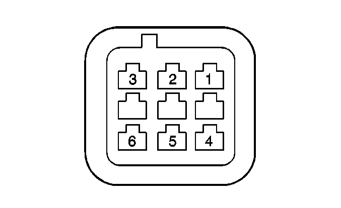
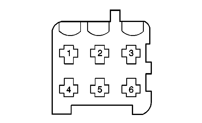
1 | GRN/YEL | Left Rear Window Switch Up Feed | 1 | GRN/YEL | Left Rear Window Switch Up Feed | ||||||||
2 | BLU/WHT | Door Lock Switch Voltage Supply | 2 | BLU/WHT | Door Lock Switch Voltage Supply | ||||||||
3 | BLU/RED | Left Rear Door Unlock Motor Feed | 3 | BLU/RED | Left Rear Door Unlock Motor Feed | ||||||||
4 | RED/YEL | Left Rear Window Switch Down Feed | 4 | RED/YEL | Left Rear Window Switch Down Feed | ||||||||
5 | -- | Not Used | 5 | -- | Not Used | ||||||||
6 | BLU | Left Rear Door Lock Motor Feed | 6 | BLU | Left Rear Door Lock Motor Feed | ||||||||
|
| ||||||||||||
|---|---|---|---|---|---|---|---|---|---|---|---|---|---|
Connector Part Information |
| Connector Part Information |
| ||||||||||
Pin | Wire Color | Function | Pin | Wire Color | Function | ||||||||
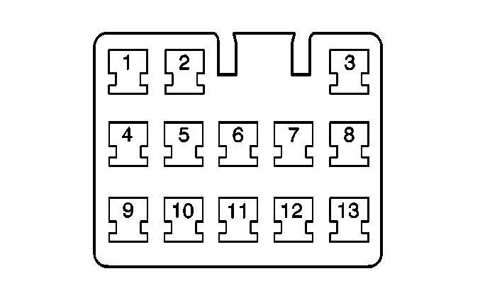
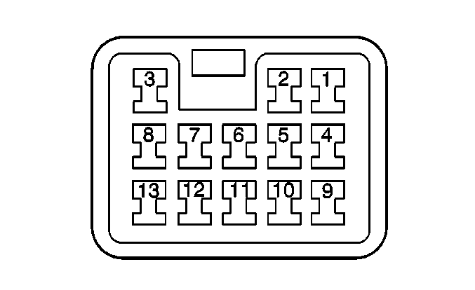
1 | ORN | Rear Wiper OFF Signal | 1 | ORN | Rear Wiper OFF Signal | ||||||||
2 | PNK | Lock Control | 2 | PNK | Lock Control | ||||||||
3 | BLK/RED | Relay Control | 3 | BLK/RED | Relay Control | ||||||||
4 | YEL/BLU | Ignition Positive Voltage | 4 | YEL/BLU | Ignition Positive Voltage | ||||||||
5 | RED/WHT | Ignition Positive Voltage | 5 | RED/WHT | Ignition Positive Voltage | ||||||||
6 | BLU | Door Lock Relay Control | 6 | BLU | Door Lock Relay Control | ||||||||
7 | GRN/WHT | Battery Positive Voltage | 7 | GRN/WHT | Battery Positive Voltage | ||||||||
8 | -- | Not Used | 8 | YEL/BLU | Not Used | ||||||||
9 | RED/YEL | Battery Positive Voltage | 9 | RED/YEL | Battery Positive Voltage | ||||||||
10 | BLU/GRN | Rear Washer OFF Signal | 10 | BLU/GRN | Rear Washer OFF Signal | ||||||||
11 | BLU/RED | Door Unlock Relay Control | 11 | BLU/RED | Door Unlock Relay Control | ||||||||
12 | -- | Not Used | 12 | -- | Not Used | ||||||||
13 | BLK | Ground-G401 | 13 | BLK | Ground-G400 | ||||||||
|
| ||||||||||||
|---|---|---|---|---|---|---|---|---|---|---|---|---|---|
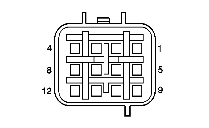
Connector Part Information |
| Connector Part Information |
| ||||||||||
Pin | Wire Color | Function | Pin | Wire Color | Function | ||||||||
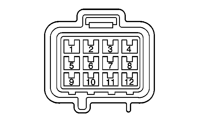
1 | BLK | Ground-G400 | 1 | BLK | Ground-G400 | ||||||||
2 | PNK/BLK | Fuel Pump Relay Output | 2 | PNK/BLK | Fuel Pump Relay Output | ||||||||
3 | BLK/YEL | Ground-G103 | 3 | BLK/YEL | Ground-G103 | ||||||||
4 | BLU/WHT | Fuel Level Input | 4 | BLU/WHT | Fuel Level Input | ||||||||
5 | -- | Not Used | 5 | -- | Not Used | ||||||||
6 | BRN/RED | Reference Voltage | 6 | BRN/RED | Reference Voltage | ||||||||
7 | GRY/YEL | Sensor Ground | 7 | GRY/YEL | Sensor Ground | ||||||||
8 | GRY/RED | Fuel Tank Pressure Input | 8 | GRY/RED | Fuel Tank Pressure Input | ||||||||
9 | YEL | RT Rear Wheel Speed Sensor Signal High | 9 | YEL | RT Rear Wheel Speed Sensor High | ||||||||
10 | YEL/BLK | RT Rear Wheel Speed Sensor Low | 10 | YEL/BLK | RT Rear Wheel Speed Sensor Low | ||||||||
11 | LT GRN | LFT Rear Wheel Speed Sensor High | 11 | LT GRN | LFT Rear Wheel Speed Sensor High | ||||||||
12 | LT GRN/BLK | LFT Rear Wheel Speed Sensor Low | 12 | LT GRN/BLK | LFT Rear Wheel Speed Sensor Low | ||||||||
|
| ||||||||||||
|---|---|---|---|---|---|---|---|---|---|---|---|---|---|
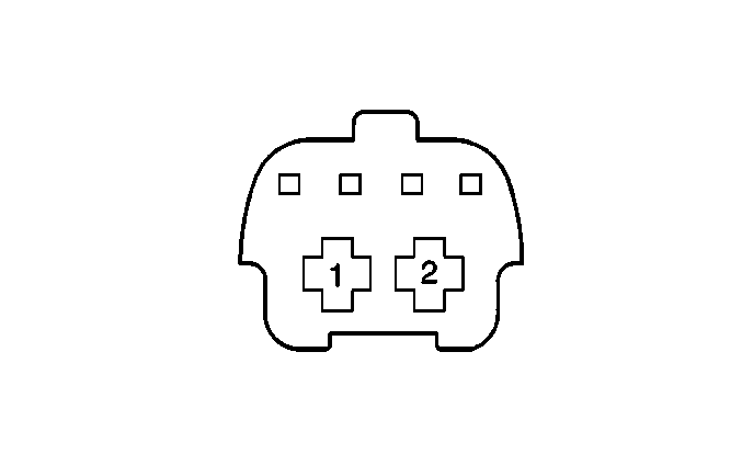
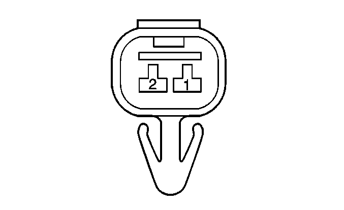
Connector Part Information |
| Connector Part Information |
| ||||||||||
Pin | Wire Color | Function | Pin | Wire Color | Function | ||||||||
1 | GRN/WHT | Battery Positive Voltage | 1 | GRN/WHT | Battery Positive Voltage | ||||||||
2 | BLK | Ground, G401 | 2 | BLK | Ground, G401 | ||||||||
