Circuit Description
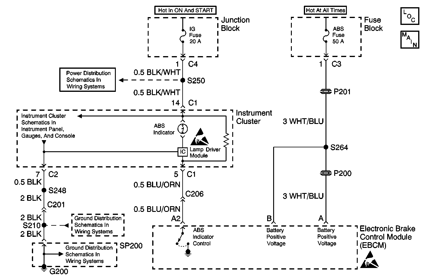
The Electronic Brake Control Module (EBCM) controls the operation of the amber ABS indicator lamp by means of a lamp driver module.
When the ignition switch is turned to the ON position, the EBCM turns ON the ABS indicator for 3 seconds for a bulb check. Whenever a malfunction is detected within the ABS system, the EBCM tuns ON the ABS indicator, notifying the driver that ABS needs to be serviced.
Diagnostic Aids
The following conditions may cause an intermittent malfunction:
| • | A poor connection |
| • | Rubbed-through wire insulation |
| • | A broken wire inside the insulation |
Thoroughly inspect any circuitry that may cause the intermittent complaint for the following conditions:
| • | Backed out terminals |
| • | Improper mating |
| • | Broken locks |
| • | Improperly formed or damaged terminals |
| • | Poor terminal-to-wiring connections |
| • | Physical damage to the wiring harness |
| • | Open IG Fuse |
| • | Open bulb filament |
| • | Open or poor G200 |
| • | Short to ground in the lamp driver module control circuit |
| • | Open within I/P gage printed circuit |
| • | Malfunctioning lamp driver module |
Test Description
The number(s) below refer to the step number(s) on the diagnostic table.
-
The Diagnostic System Check must be the starting point for any ABS related diagnosis.
-
Tests for power distribution to the instrument panel gage cluster and EBCM.
-
Tests the ABS Indicator Control and the Battery Positive Voltage circuits for a short to ground.
-
Ensures the fault is not in the Lamp Driver Module.
Step | Action | Value(s) | Yes | No |
|---|---|---|---|---|
Was the ABS Diagnostic System Check performed? | -- | Go to Step 2 | ||
Remove and inspect the IG Fuse and the ABS Fuse. Is either of the fuses open? | -- | Go to Step 3 | Go to Step 4 | |
3 |
Did you find and correct the condition? | -- | Go to Testing for Intermittent Conditions and Poor Connections | |
Did you find and correct the condition? | -- | Go to Step 5 | ||
5 | Test the EBCM and IP ground circuits for an open or high resistance. Refer to Circuit Testing and Wiring Repairs in Wiring Systems. Did you find and correct the condition? | -- | Go to Step 6 | |
6 | Remove and inspect the ABS Indicator bulb. Refer to Instrument Cluster Bulb Replacement in Instrument Panel, Gauges, and Console. Replace the bulb if necessary. Did you find and correct the condition? | -- | Go to Step 7 | |
Does the ABS indicator turn ON when commanded with the scan tool? | -- | Go to Step 8 | ||
8 | Replace the electronic brake control module. Refer to Electronic Brake Control Module Replacement . Did you complete the replacement? | -- | -- |
