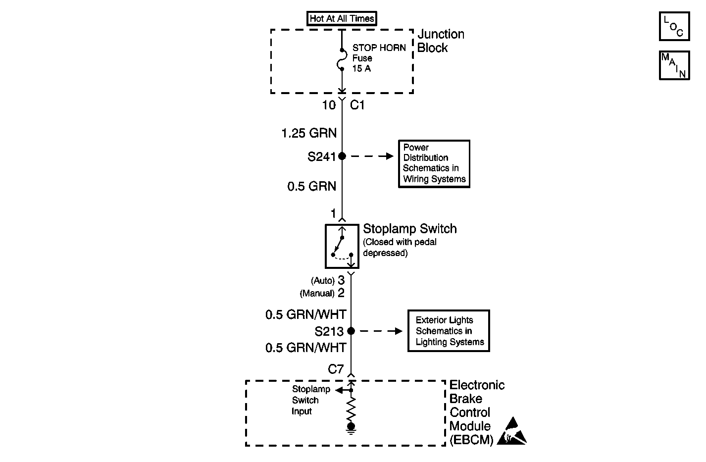
Circuit Description
DTC C1295 identifies open brake switch circuitry that prevents the brake switch input to the EBCM from changing states while applying the brake. An open brake switch circuit will result in a modified ABS entrance criteria and possibly false settings of excessive wheel speed variation codes (C1225 thru C1228).
Conditions for Running the DTC
This DTC can set anytime that the EBCM is powered.
Conditions for Setting the DTC
The brake switch input voltage is between 2.2 volts and 5.0 volts for 2.0 seconds.
Action Taken When the DTC Sets
ABS remains functional.
Conditions for Clearing the DTC
| • | The condition responsible for setting the DTC no longer exists and the Scan Tool Clear DTCs function is used. |
| • | 100 drive cycles pass with no DTCs detected. A drive cycle consists of starting the vehicle, driving the vehicle over 16 km/h (10 mph), stopping and then turning the ignition OFF. |
Diagnostic Aids
Possible causes:
| • | Stoplamp switch input circuit open. |
| • | The brake switch is misadjusted. |
| • | All brake lamps open. |
| • | Open brake lamp ground. |
The following conditions may cause an intermittent malfunction:
| • | A poor connection |
| • | Rubbed-through wire insulation |
| • | A broken wire inside the insulation |
Use the enhanced diagnostic function of the Scan Tool in order to measure the frequency of the malfunction.
Thoroughly inspect any circuitry that may cause the intermittent complaint for the following conditions:
| • | Backed out terminals |
| • | Improper mating |
| • | Broken locks |
| • | Improperly formed or damaged terminals |
| • | Poor terminal-to-wiring connections |
| • | Physical damage to the wiring harness |
| • | Open stoplamp switch electrical circuit |
| • | Malfunctioning stoplamp bulb electrical circuit (open/high resistance to ground) |
| • | If an intermittent malfunction exists refer to Testing for Intermittent Conditions and Poor Connections in Wiring Systems. |
Test Description
The number below refers to the step number on the diagnostic table.
Step | Action | Value(s) | Yes | No |
|---|---|---|---|---|
1 | Did you perform the ABS Diagnostic System Check? | -- | Go to Step 2 | |
2 | Press the brake pedal. Do the brake lamps turn ON? | -- | Go to Step 3 | Go to Exterior Lights System Check in Lighting Systems |
3 |
Does the scan tool display that the Brake Switch Status is ON? | -- | Go to Testing for Intermittent Conditions and Poor Connections in Wiring Systems | Go to Step 4 |
Did you find and correct the condition? | -- | Go to Step 7 | Go to Step 5 | |
5 | Inspect for poor connections at the harness connector of the EBCM. Refer to Testing for Intermittent Conditions and Poor Connections and Connector Repairs in Wiring Systems. Did you find and correct the condition? | -- | Go to Step 7 | Go to Step 6 |
6 | Replace the EBCM. Refer to Electronic Brake Control Module Replacement . Did you complete the replacement? | -- | Go to Step 7 | -- |
7 |
Does the DTC reset? | -- | Go to Step 2 | System OK |
