Removal Procedure
Caution: Wrap a shop towel around the fuel pressure connection in order to reduce the risk of fire and personal injury. The towel will absorb any fuel leakage that occurs during the connection of the fuel pressure gage. Place the towel in an approved container when the connection of the fuel pressure gage is complete.
Notice: Upon disassembly of the fuel system components, use a shop towel in order to absorb any liquid fuel that is released. A significant amount of liquid fuel entering an engine cylinder can damage internal engine parts upon the compression stroke.
- Relieve the fuel pressure. Refer to Fuel Pressure Relief .
- Remove the throttle body assembly. Refer to Throttle Body Assembly Replacement .
- Disconnect the fuel injector electrical connectors.
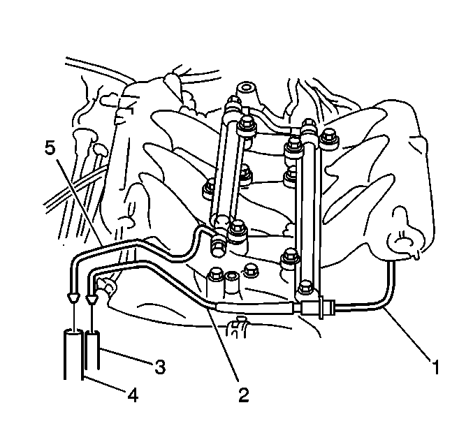
- Remove the fastener securing the fuel supply pipe (5) and the fuel return pipe (2) to the engine.
- Disconnect the vacuum hose (1) to the fuel pressure regulator.
- Disconnect the fuel return hose (3) from the fuel pressure regulator. Use a shop towel in order to catch any remaining fuel that may leak.
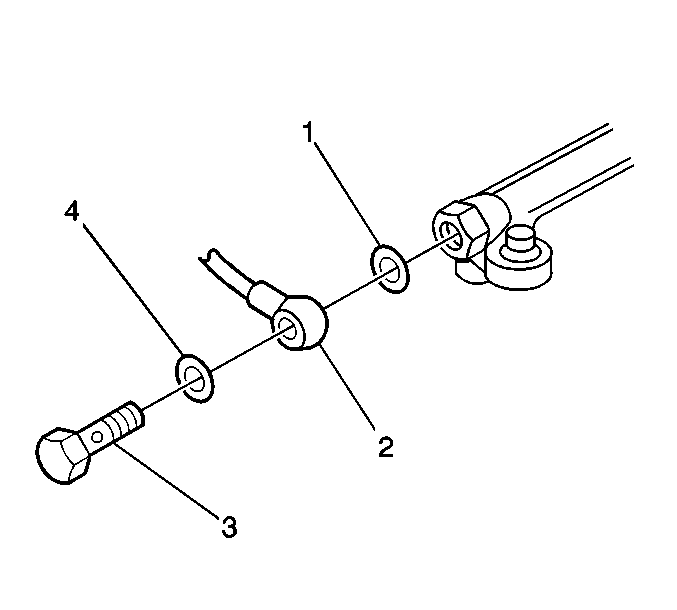
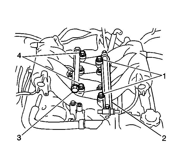
- Remove the union bolt (3) that secures the fuel supply pipe (2) to the fuel rail. Use a shop towel in order to catch any remaining fuel that may leak.
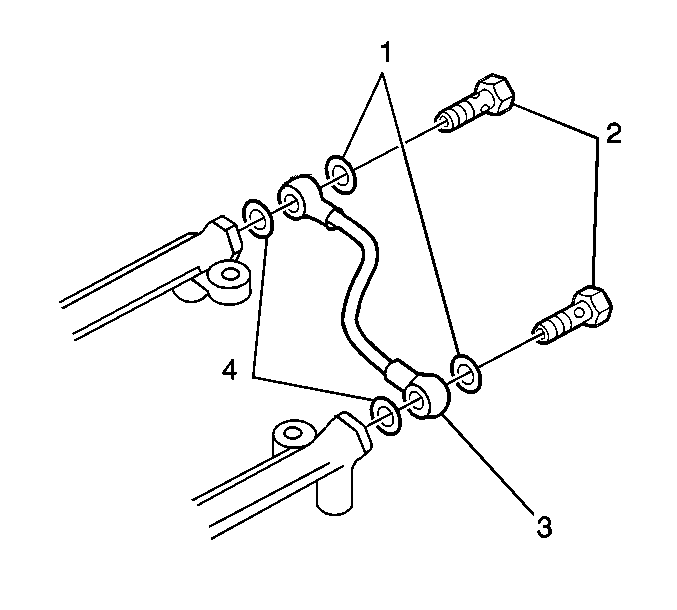
- Remove the two union bolts (2) securing the fuel rail crossover pipe (3) at the rear of the fuel rails. Use a shop towel in order to catch any remaining fuel that may leak.
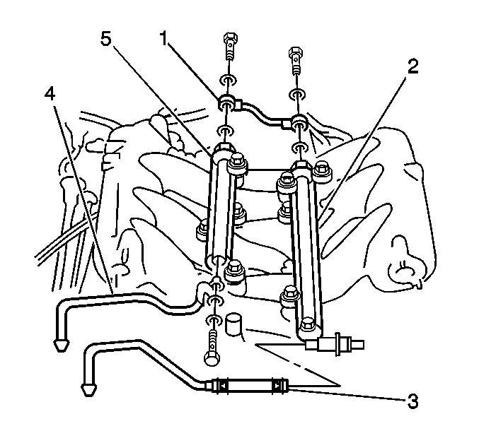
- Remove the two hold down bolts (1) from the left fuel rail (2). Use a shop towel in order to catch any remaining fuel that may leak.
- Remove the left fuel rail (2) and fuel injectors.
- Remove the two hold down bolts (4) from the right fuel rail (3). Use a shop towel in order to catch any remaining fuel that may leak.
- Remove the right fuel rail (3) and fuel injectors. Use a shop towel in order to catch any remaining fuel that may leak.
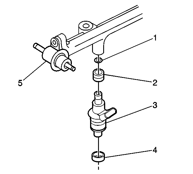
- Remove the fuel injectors (3) from the fuel rail as necessary.
Installation Procedure
- Apply a thin coat of motor oil to the fuel injector O-rings (1).
- Install a fuel injector O-ring (1) with a collar (2) to each fuel injector (3).
- Install each fuel injector (3) to the fuel rail.
- Prepare each fuel rail assembly for installation, by ensuring that the cushions (4) are properly located in the fuel injector cavity of the intake manifold. Replace any missing or damaged cushions as necessary.
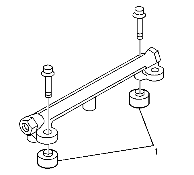
- Install the left fuel rail to the intake manifold with two bolts and two spacers (1).
- Install the right fuel rail to the intake manifold with two bolts and two spacers (1).
- Verify that the fuel injectors rotate smoothly and freely.
- Install the fuel rail crossover pipe (3) to the fuel rails, using new washers (1, 4) and securing with the two union bolts (2).
- Install the fuel supply pipe (2) to the right side fuel rail with two new washers (1, 4).
- Secure the fuel supply pipe (2) with the union bolt (3).
- Connect the fuel return hose (3) to the fuel pressure regulator.
- Secure the fuel supply pipe (5) and the fuel return pipe (2) to the engine with the bracket and bolt.
- Connect the battery.
- Turn ON the ignition, leaving the engine OFF.
- Turn ON the fuel pump with the scan tool.
- Check for fuel leaks and repair as necessary.
- Install the throttle body assembly. Refer to Throttle Body Assembly Replacement .

Important: Always replace the fuel injector O-rings with new O-rings when servicing the fuel injectors. Do not damage the O-rings during the installation.
Important: Inspect the fuel injector cushions for scoring or for damage. Before installing the fuel injectors to the intake manifold, replace any faulty injector cushions .
Notice: Use the correct fastener in the correct location. Replacement fasteners must be the correct part number for that application. Fasteners requiring replacement or fasteners requiring the use of thread locking compound or sealant are identified in the service procedure. Do not use paints, lubricants, or corrosion inhibitors on fasteners or fastener joint surfaces unless specified. These coatings affect fastener torque and joint clamping force and may damage the fastener. Use the correct tightening sequence and specifications when installing fasteners in order to avoid damage to parts and systems.
Tighten
Tighten the bolts to 23 N·m (16.5 lb ft).
Tighten
Tighten the bolts to 23 N·m (16.5 lb ft).
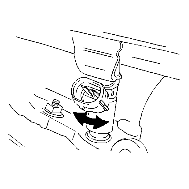
Important: An incorrectly installed fuel injector O-ring can prevent the fuel injector from rotating freely. Inspect for binding fuel injector O-rings, and replace any O-rings as necessary.

Tighten
Tighten the union bolts to 30 N·m (22 lb ft).

Tighten
Tighten the union bolt to 30 N·m (22 lb ft).


Tighten
Tighten the bolt to 10 N·m (89 lb in).
Connect the fuel injector electrical connectors.
