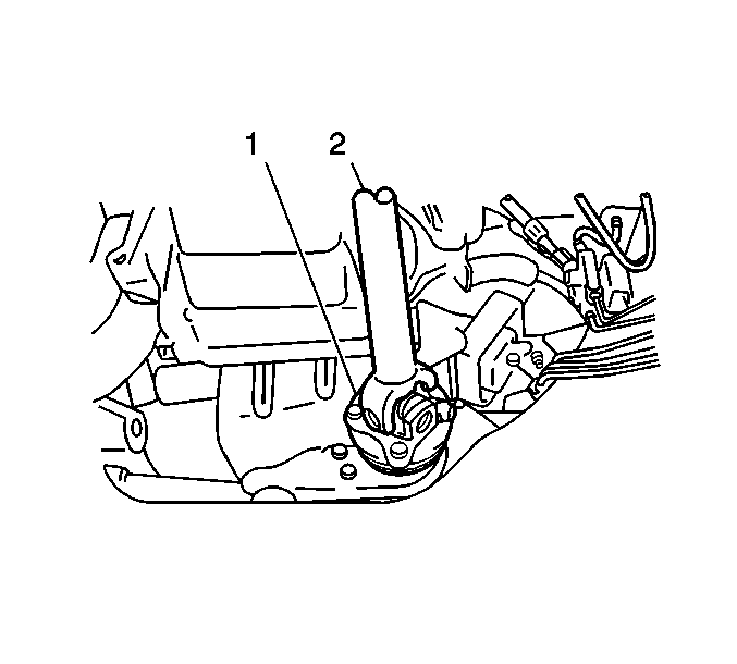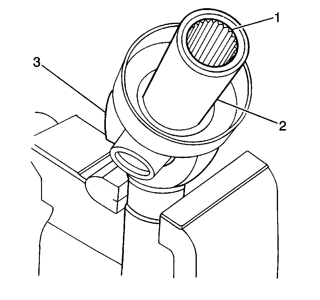
- Install the sliding yoke
into the transfer case.
Notice: Use the correct fastener in the correct location. Replacement fasteners
must be the correct part number for that application. Fasteners requiring
replacement or fasteners requiring the use of thread locking compound or sealant
are identified in the service procedure. Do not use paints, lubricants, or
corrosion inhibitors on fasteners or fastener joint surfaces unless specified.
These coatings affect fastener torque and joint clamping force and may damage
the fastener. Use the correct tightening sequence and specifications when
installing fasteners in order to avoid damage to parts and systems.
- Install the pinion
flange yoke to the differential pinion flange (1) aligning index marks
on the pinion flange yoke and differential pinion flange. Secure
the pinion flange yoke with 4 bolts and the 4 nuts.
Tighten
Tighten the propeller shaft bolts and nuts to 50 N·m (37 lb ft).
If the vehicle is equipped with a transfer case, apply GM P/N 12346004,
or equivalent, to the threaded portion of the transfer case drain plug.
- If the vehicle is equipped with a transfer case, install the transfer
case drain plug into the transfer case.
Tighten
Tighten the transfer case drain plug to 28 N·m (21 lb ft).
- If the vehicle is equipped with a transfer case, refill the transfer
case with approximately 1.7 liters (1.8 quarts) of 75W90 GL4
synthetic lubricant GM P/N 12346190 (Canadian P/N 10953477),
or equivalent.
- If the vehicle is equipped with a transfer case, apply GM P/N 12346004
(Canadian P/N 10953480), or equivalent, to the threaded portion
of the transfer case oil level filler plug.
- If the vehicle is equipped with a transfer case, install the transfer
case oil level/filler plug into the transfer case.
Tighten
Tighten the transfer case oil level/filler plug to 28 N·m
(21 lb ft).
- If the vehicle is equipped with a transfer case, remove the drain
pan from underneath the transfer case.
- Lower the vehicle.


