Removal Procedure
Caution: Unless directed otherwise, the ignition and start switch must be in the OFF or LOCK position, and all electrical loads must be OFF before servicing
any electrical component. Disconnect the negative battery cable to prevent an electrical spark should a tool or equipment come in contact with an exposed electrical terminal. Failure to follow these precautions may result in personal injury and/or damage to
the vehicle or its components.
- Disconnect
the negative battery cable.
- Remove the engine front cover. Refer to
Engine Front Cover Replacement
.
- Remove the spark plugs. Refer to
Spark Plug Replacement
in Engine Controls -2.5L.
Notice: Avoid turning the camshafts and the crankshaft once the timing chain
or timing chain tensioner is removed. Valve and piston damage may occur.
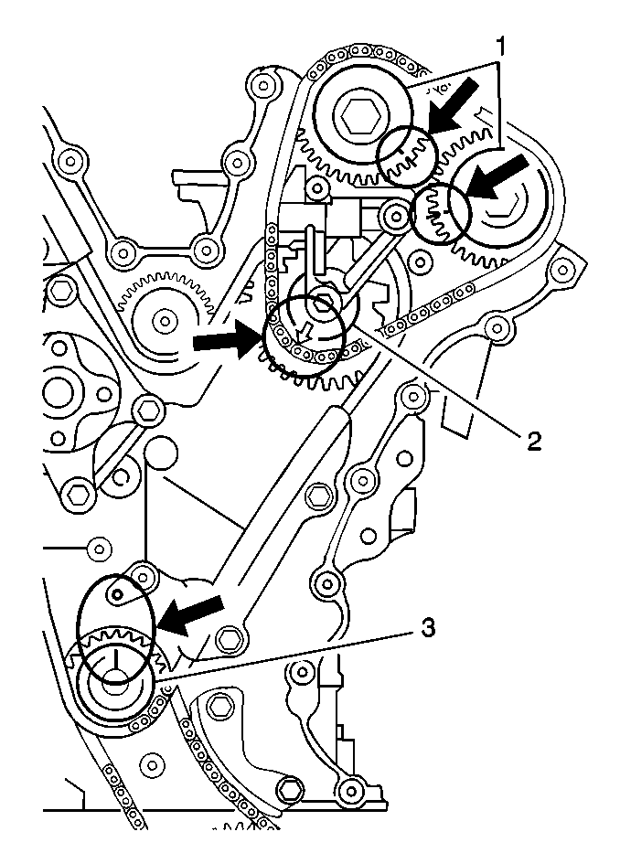
Important: The timing marks must be correctly aligned before disassembly in order
to correctly install the timing chains.
- Rotate the crankshaft so that the following conditions are met:
| • | The keyway on the crankshaft (3) is properly positioned. |
| • | The arrow (2) on the idler sprocket is pointing to the
crankshaft. |
| • | The marks on the sprockets (1) match up with the marks
on the cylinder head. |
- Remove the 3 bolts and the upper chain guide.
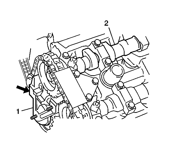
- Remove the 1 nut
and 2 bolts from the timing chain tensioner (1).
- Remove the timing chain tensioner (1). It may be necessary
to slacken the timing chain by turning the intake camshaft (2) counterclockwise
a little while pushing back on the tensioner pad.
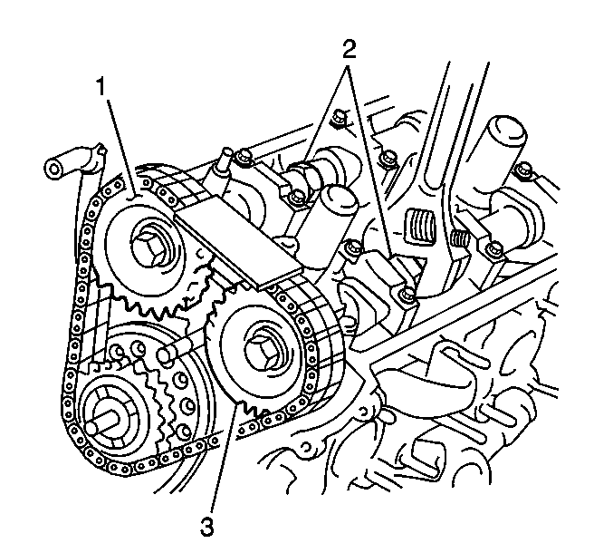
- Hold the camshafts (2)
with a wrench and remove the camshaft sprocket bolts.
- Remove the camshaft sprockets (1,3) and timing chain.
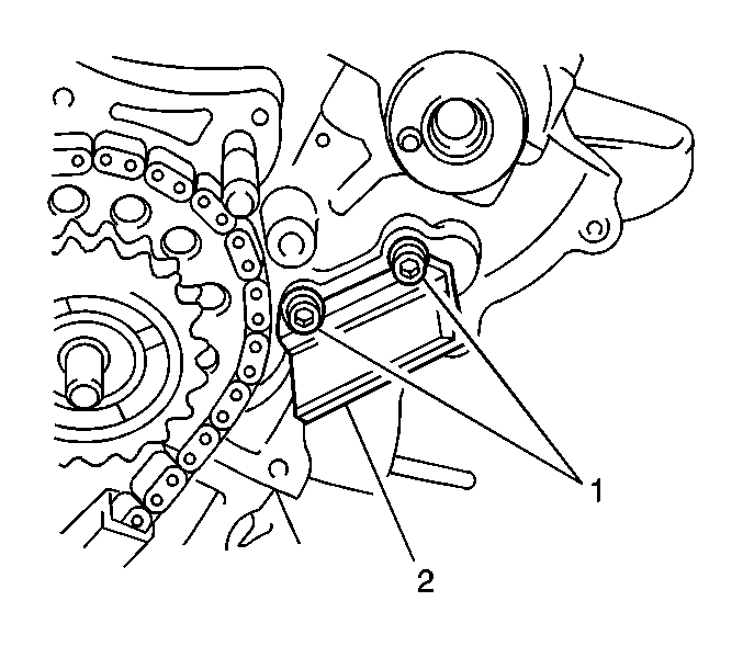
- Remove the 2 bolts (1)
and the side chain guide (2).
- Inspect the following components for wear and damage:
| • | The camshaft timing chain guides |
| • | The camshaft timing chain tensioner |
| • | The camshaft timing chain sprockets |
| • | The camshaft timing chain |
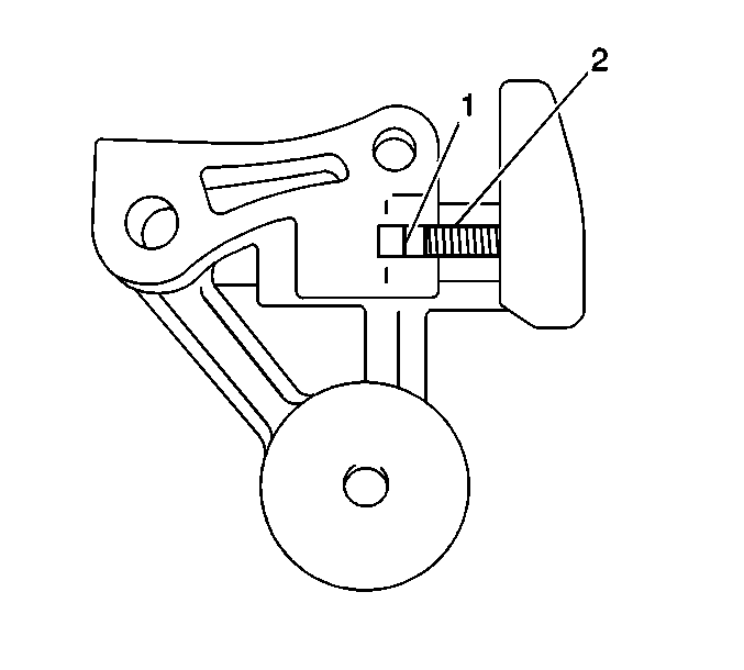
- Verify that the latch (1)
and teeth (2) of the timing chain tensioner are undamaged and that
the tensioner functions correctly.
- Replace any worn or damaged component.
Installation Procedure
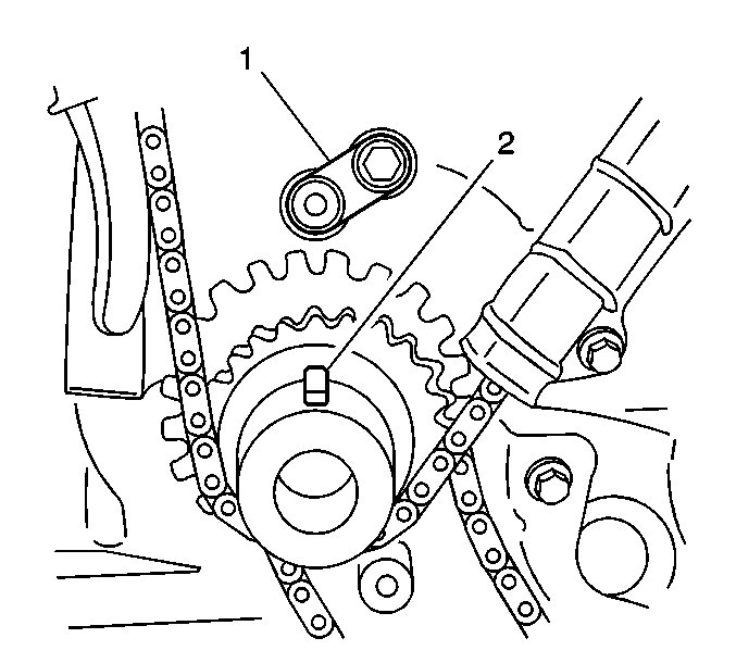
- Verify that the keyway
on the crankshaft (2) is properly positioned.
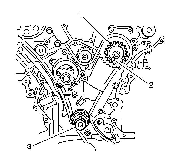
- Verify that the timing
mark (2) on the idler sprocket (1) is properly positioned.

Notice: Use the correct fastener in the correct location. Replacement fasteners
must be the correct part number for that application. Fasteners requiring
replacement or fasteners requiring the use of thread locking compound or sealant
are identified in the service procedure. Do not use paints, lubricants, or
corrosion inhibitors on fasteners or fastener joint surfaces unless specified.
These coatings affect fastener torque and joint clamping force and may damage
the fastener. Use the correct tightening sequence and specifications when
installing fasteners in order to avoid damage to parts and systems.
- Install the side
chain guide (2). Secure with the 2 bolts (1).
Tighten
Tighten the bolts to 11 N·m (7.5 lb ft).
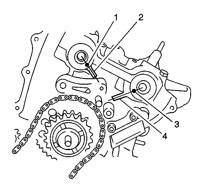
- Verify that the knock-pin (1)
of the intake camshaft and knock-pin (3) of the exhaust camshaft are
aligned with the match marks on the cylinder head.
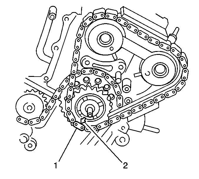
- Install the timing chain
to the idler sprocket by aligning the yellow link (1) of the timing
chain with the mark (2) on the idler sprocket.
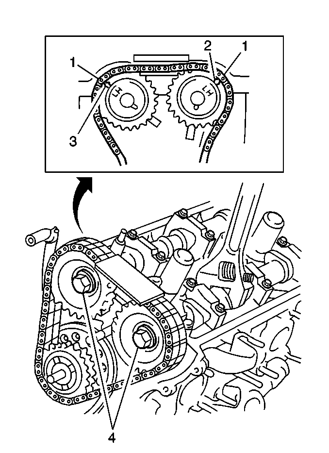
- Install the sprockets
to the camshafts by aligning the silver links (1) with the mark on
the intake sprocket (3) and the exhaust sprocket (2).
- Secure the sprocket with the bolts (4) while holding the
camshafts with a wrench.
Tighten
Tighten the 2 bolts to 80 N·m (57.5 lb ft).
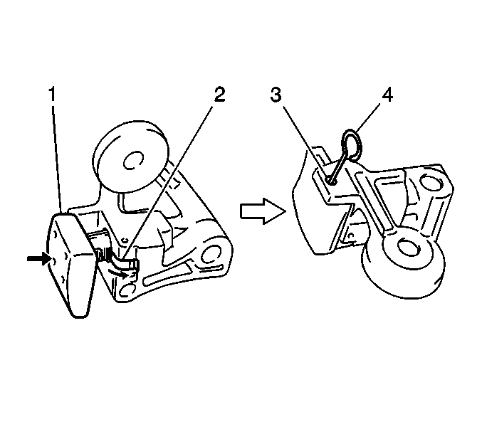
- With the latch (2)
of the tensioner adjuster returned and the plunger (1) pushed back
into the body, insert a retainer (4) (paper clip or similar tool)
into the set hole (3). After inserting the pin, make sure the
plunger will not come out.
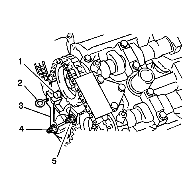
- Install the timing chain
tensioner (3). Secure with the bolt (1).
Tighten
Tighten the bolt to 12 N·m (8.5 lb ft).
- Install tensioner nut (4).
Tighten
Tighten the nut to 45 N·m (32.5 lb ft).
- Install tensioner nut (5).
Tighten
Tighten the nut to 45 N·m (32.5 lb ft).
- Remove the retainer (2) from the tensioner.
- Install the upper chain guide. Secure with the 3 bolts.
Tighten
Tighten the bolts to 11 N·m (7.5 lb ft).
- Turn the crankshaft 2 revolutions clockwise.
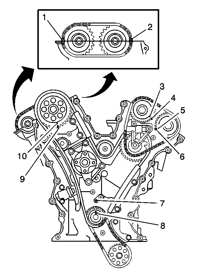
- Align the keyway (8)
on the crankshaft with the oil jet (7).
- Verify that all the other timing marks are properly aligned.
- Apply engine oil to the following:
- Install the spark plugs. Refer to
Spark Plug Replacement
in Engine Controls - 2.5L.
- Install the engine front cover. Refer to
Engine Front Cover Replacement
.
- Connect the negative battery cable.


