The air induction system draws outside air into the combustion
chamber. The intake air flows through a forward mounted duct and into the
air cleaner assembly. The intake air passes out of the air cleaner assembly,
through the mass air flow sensor and inlet duct, to the throttle body.
The throttle body houses a throttle valve that controls the volume of
air entering the intake manifold. A metered amount of air also enters
the intake manifold through the idle air bypass passage that is controlled
by the idle air control (IAC) valve. From the throttle body the intake air
flows into the intake collector and is then distributed to the bank 1
and the bank 2 cylinders through the intake manifold. The intake
air is mixed with fuel from the fuel injectors at the entrance to the
combustion chamber.

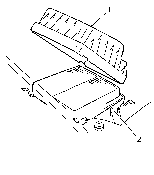
An air filter element (2) is incorporated into the air cleaner assembly
(1) in order to prevent dirt from entering the engine. The following components
are directly or indirectly a part of the air supply system.
Mass Air Flow (MAF) Sensor

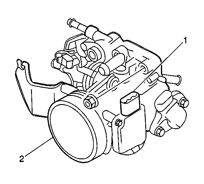
The mass air flow (MAF)
sensor is of the thermal control type. The MAF sensor consists of a
heat resistor element located inside the bore of the throttle body, an
air straightening screen (2), and a control circuit board (1).
The heat resistor is cooled off by the air entering the MAF sensor.
The control circuit maintains the heat resistor temperature within
a predetermined range. When the amount of air entering the sensor
increases, the signal created by the sensor and sent to the powertrain
control module (PCM), also increases. When the air flow decreases,
so does the signal current to the PCM. The MAF sensor is an integral
part of the throttle body.
The mass air flow (MAF) sensor measures the amount of air which passes
over the heat resistor in a given amount of time. The PCM uses this information
in order to determine the operating requirements of the engine
and control fuel delivery. A large quantity of air movement indicates
acceleration, while a small quantity indicates deceleration or
idle.
Throttle Body Assembly

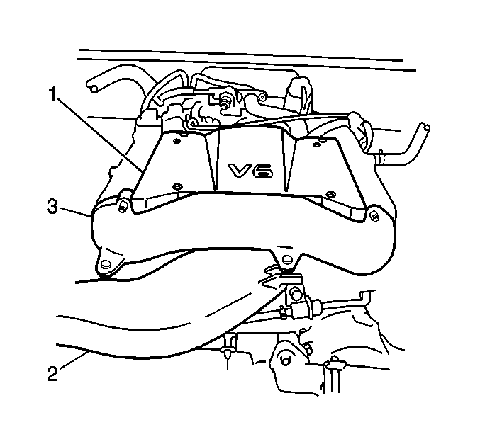
The throttle body assembly
is located underneath the engine surge tank cover (1), between the air inlet
duct (2) and the intake collector. The following components and parts
make up the throttle body assembly:
| • | Idle air bypass passage |
| • | Throttle position sensor |
The throttle valve is interlocked with the accelerator pedal by the
accelerator control cable. The throttle valve controls the large volume of
air that is drawn into the intake chamber. The idle air bypass passage
provides air for the control of engine speed when the throttle valve
is closed. The fast idle-up valve provides additional bypass air to
engine when the engine is cold. The fast idle-up valve is preset at
the factory and cannot be adjusted. The fast idle-up valve is not serviced
separate from the throttle body assembly. The throttle body is warmed
by engine coolant that flows through a coolant passage located near
the fast idle-up valve. The warming of the throttle body also helps prevent
throttle valve icing. The throttle body also houses the components of
the MAF sensor.
Engine Idle Speed Control Operation
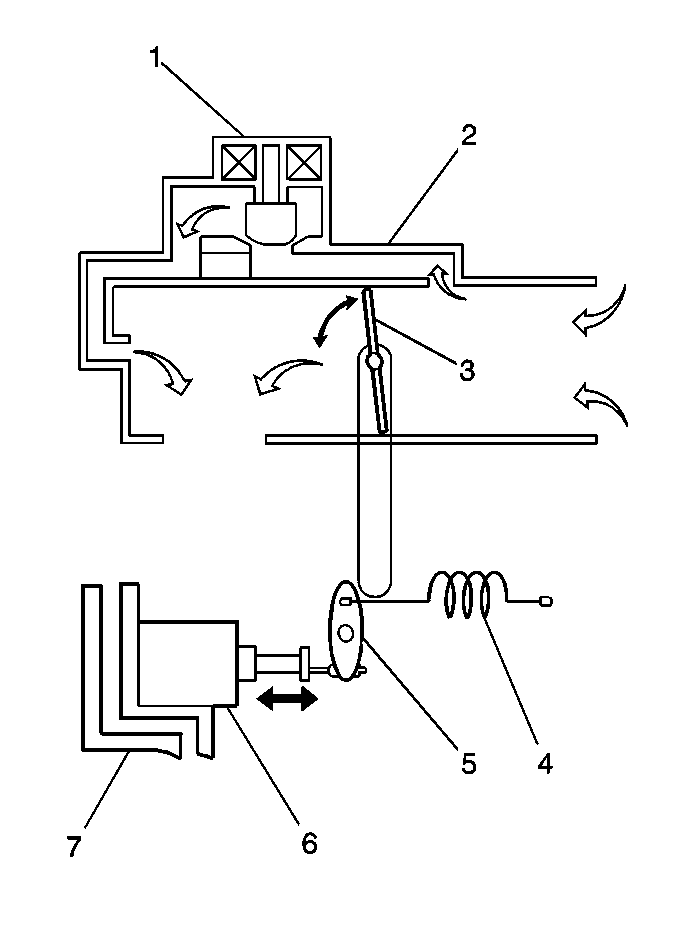
The engine idle speed is controlled by the powertrain control module
(PCM) through the idle air control (IAC) valve which allows more or less air
to bypass the throttle valve. There are several reasons for idle
speed control:
- Maintain the engine idle speed at the specified RPM at all times.
The engine idle speed can vary due to any of the following reasons:
| • | A change in atmospheric pressure. |
| • | A change in the engine's condition over time. |
| • | Other factors causing the idle speed to change. |
- Improve the driveability of the engine during warm up.
- Compensate for the change in the air/fuel mixture ratio when decelerating
(dash-pot effect).


