Removal Procedure
- Drain the engine cooling system. Refer to
Cooling System Draining and Filling
in Engine Cooling.
- Remove the instrument panel (IP) carrier. Refer to
Instrument Panel Assembly Replacement
in Instrument Panel, Gages
and Console.
- Remove the heater hoses and clamps from the heater core. Refer to
Heater Hoses Replacement
.
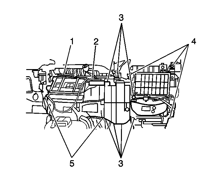
- Disconnect the electrical connector from the A/C compressor control
module (2) , if equipped.
- Remove the A/C compressor control module (2) , if equipped.

- Remove
the 2 nuts and 6 screws (3) from the air box.
- Remove the air box from the vehicle. If equipped with A/C, remove the
evaporator. Refer to
Air Conditioning Evaporator Core Replacement
in A/C Manual.

- If necessary to remove the blower case, perform the following:
| 8.1. | Disconnect the blower motor electrical connector. |
| 8.2. | Disconnect the blower motor resistor electrical connector. |
| 8.3. | Remove the fresh/recirc control cable from the blower case. |
| 8.4. | Remove the 1 screw and the blower relay bracket from the blower
case. |
| 8.5. | Remove the wiring harness retainers from the blower case. |
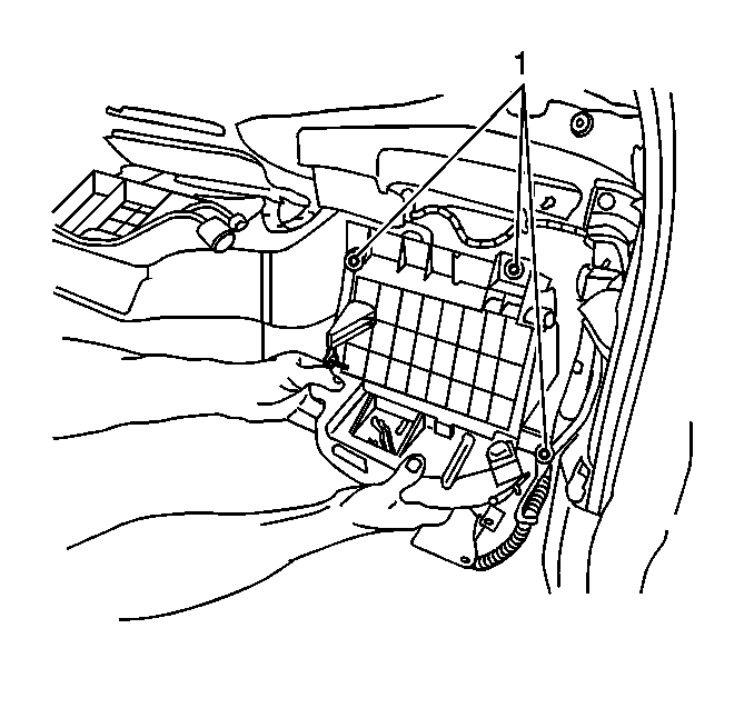
| 8.7. | Remove the 4 nuts (1). |
| 8.8. | Remove the blower case from the vehicle. |

- Remove
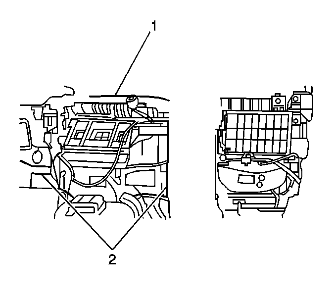
the nut from the center of the bulkhead on the engine side (1).
- Remove the 2 nuts from the heater case (2).
- Separate the floor ducts from the heater case.
- Remove the heater case from the vehicle.
Disassembly Procedure
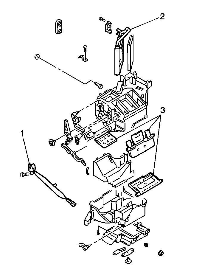
- Remove the 8 retaining clips from the heater case.

- Remove the screw and the blend door linkages.
- Separate the heater case halves.
- Remove and replace the following components as necessary:
Assembly Procedure

- Install the following components as necessary:
- Position the heater case halves together.
- Install the 8 retaining clips to the heater case.
- Install the blend door linkages and secure with the screw.
Installation Procedure
- Install the heater case to the vehicle.
- Connect the floor ducts to the heater case.

- Install
the nut to the center of the bulkhead on the engine side (1).
Notice: Use the correct fastener in the correct location. Replacement fasteners
must be the correct part number for that application. Fasteners requiring
replacement or fasteners requiring the use of thread locking compound or sealant
are identified in the service procedure. Do not use paints, lubricants, or
corrosion inhibitors on fasteners or fastener joint surfaces unless specified.
These coatings affect fastener torque and joint clamping force and may damage
the fastener. Use the correct tightening sequence and specifications when
installing fasteners in order to avoid damage to parts and systems.
- Install the 2 nuts to the heater case (2).
Tighten
Tighten the heater case nuts to 10 N·m (89 lb in).

- If the blower case was removed, perform the following:
| 5.1. | Install the blower case to the vehicle. Secure with the 4 nuts (1). |
Tighten
Tighten the nuts to 10 N·m (89 lb in).
| 5.2. | Connect the blower motor electrical connector. |
| 5.3. | Connect the blower motor resistor electrical connector. |
| 5.4. | Install the fresh/recirc control cable to the blower case. Adjust the
cable as necessary, refer to
Vent Control Cable Adjustment
in
HVAC Systems - Manual. |
| 5.5. | Install the blower relay bracket to the blower case. Secure with the
screw. |
| 5.6. | Install the wiring harness retainers to the blower case. |

- Install
the air box or the A/C evaporator, if equipped. Refer to
Air Conditioning Evaporator Core Replacement
in A/C Manual. Secure with the 2 nuts
and 6 screws (3).
Tighten
Tighten the nuts and screws to 10 N·m (89 lb in).
- Install the A/C compressor control module (2), if equipped.
- Connect the electrical connector to the A/C compressor control module (2),
if equipped.
- Install the heater hoses and clamps to the heater core. Refer to
Heater Hoses Replacement
.
- Install the instrument panel. Refer to
Instrument Panel Assembly Replacement
in Instrument Panel, Gages and Console.
- Fill the engine cooling system. Refer to
Cooling System Draining and Filling
in Engine Cooling.


