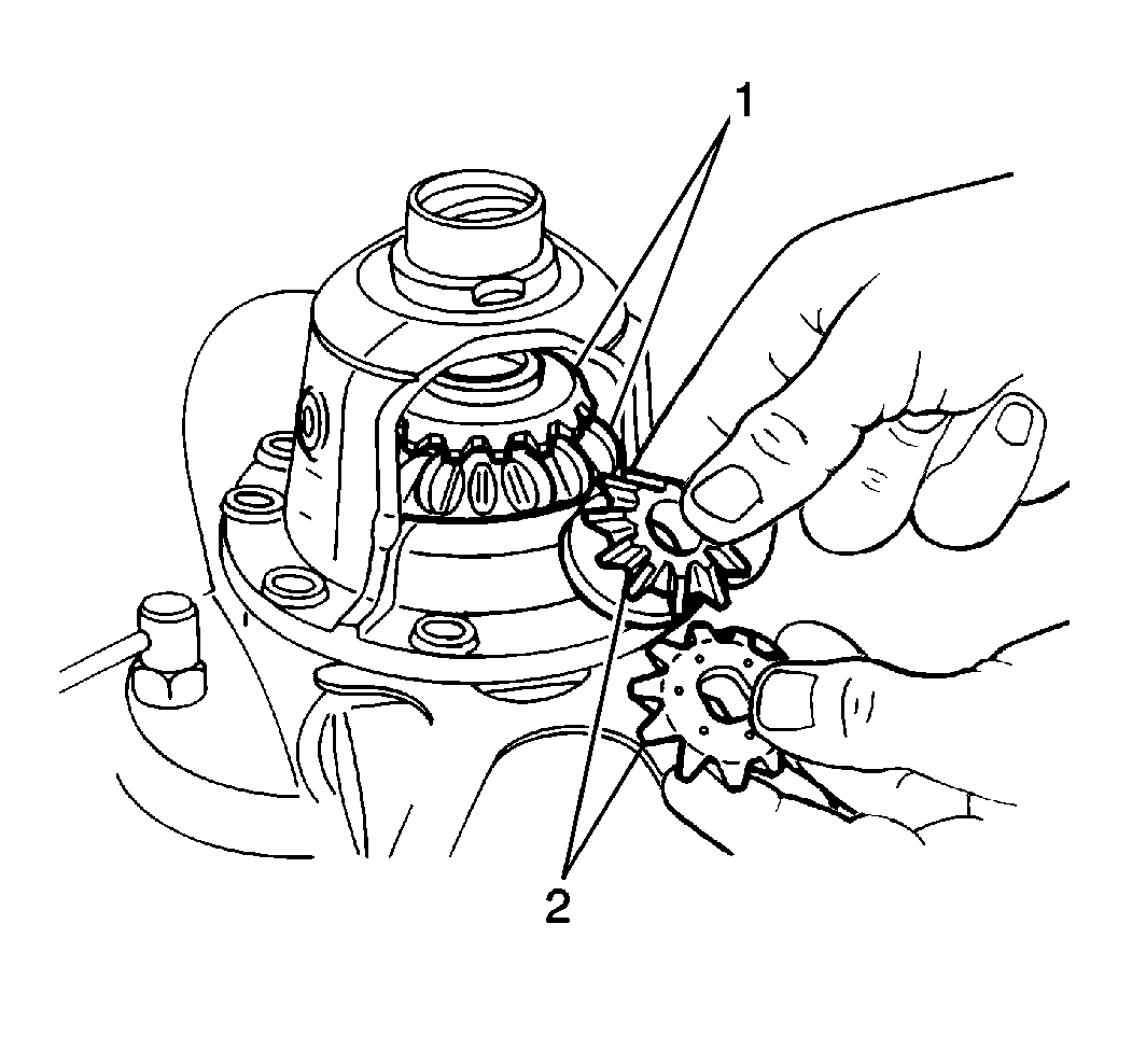
- Install the following
into the differential case:
| • | The Differential pinion gears (2) |
- Install the pinion shaft into the differential case.
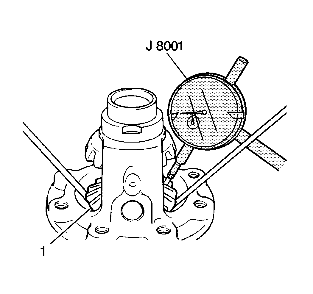
| • | Measure the left differential
side gear (1) end play using the J 8001
. |
| - | Place the plunger between the teeth of the left side gear
and move the left side gear up and down using 2 screw drivers
while observing the J 8001
. |
| - | The left side gear end play should measure 12 to 37 mm
(0.005 to 0.014 in). |
| - | If the left side gear end play is too high or low, replace
the side gear selective washer with the appropriate size to obtain
correct end play. |
| • | Measure the right differential side gear (1) end play using
the J 8001
. |
| - | Place the plunger on the rear of the right differential side
gear and using the finger tips of both hands, gently move the
right differential side gear up and down while observing the J 8001
. |
| - | The side gear end play should measure 12 to 37 mm (0.005
to 0.014 in). |
| - | If the side gear end play is too high or low, replace the
side gear selective washer with the appropriate size to obtain
correct end play. |
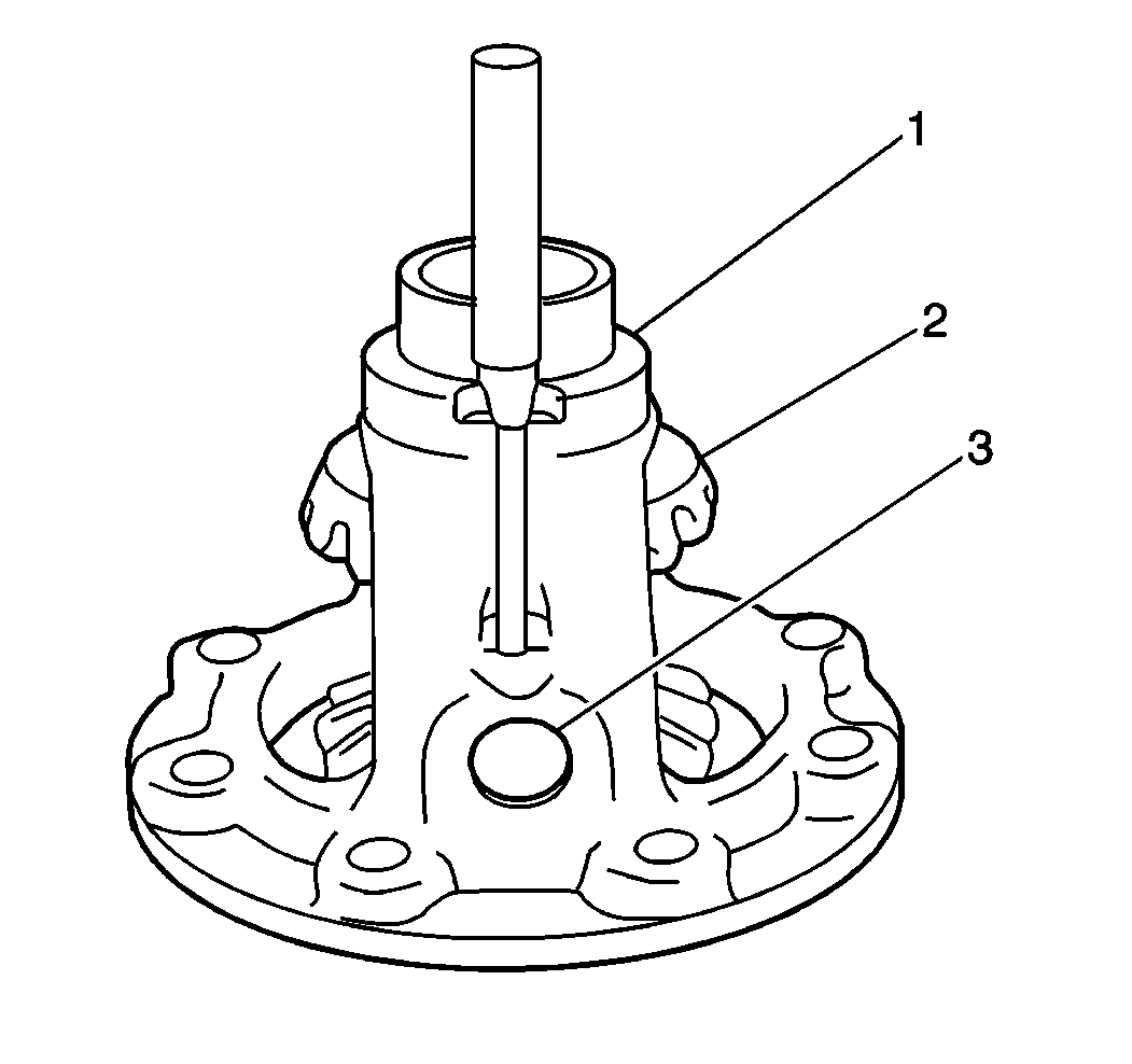
- Install the pinion shaft
roll pin into the differential case (1) and through the pinion shaft (3).
The roll pin end should be even with the differential case
surface.
Notice: Refer to Fastener Notice in the Preface section.
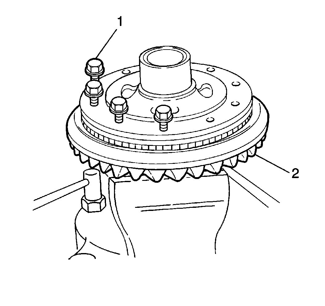
Important: After correct end play has been obtained, remove the ring gear bolts (1)
and apply GM P/N 12345493, or equivalent, to the threaded
portion of each ring gear bolt and install into the differential
case.
- Install the ring gear (1) to the differential case. Secure with
10 bolts.
Tighten
Tighten the ring gear bolts to 85 N·m (63 lb ft).
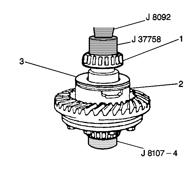
- Install the actuator (3)
to the differential case assembly (2).
- Install the side bearing (1) on the left side of the differential
case (2) assembly using the J 37758
with the J 8092
.
| • | Place the differential case assembly on a hydraulic press. |
| • | Use the J 37758
with the J 8092
in order to place the left differential side bearing on
the left differential case with the tapered side up and
slowly press the left differential side bearing onto the
left differential case. |
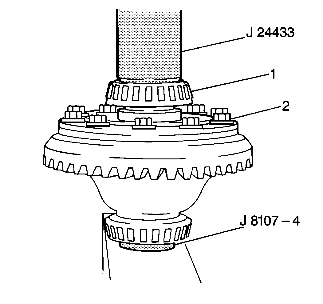
- Install the side bearing (1)
on the right side of the differential case assembly (2) using the J 24433
with the J 8092
and J 8107-4
.
| • | Place the differential case assembly on a hydraulic press
using the J 8107-4
for support and to protect the left differential side
bearing. |
| • | Use the J 24433
with the J 8092
in order to place the right differential side bearing on
the right differential case with the tapered side up and slowly
press the right differential side bearing onto the right differential
case. |
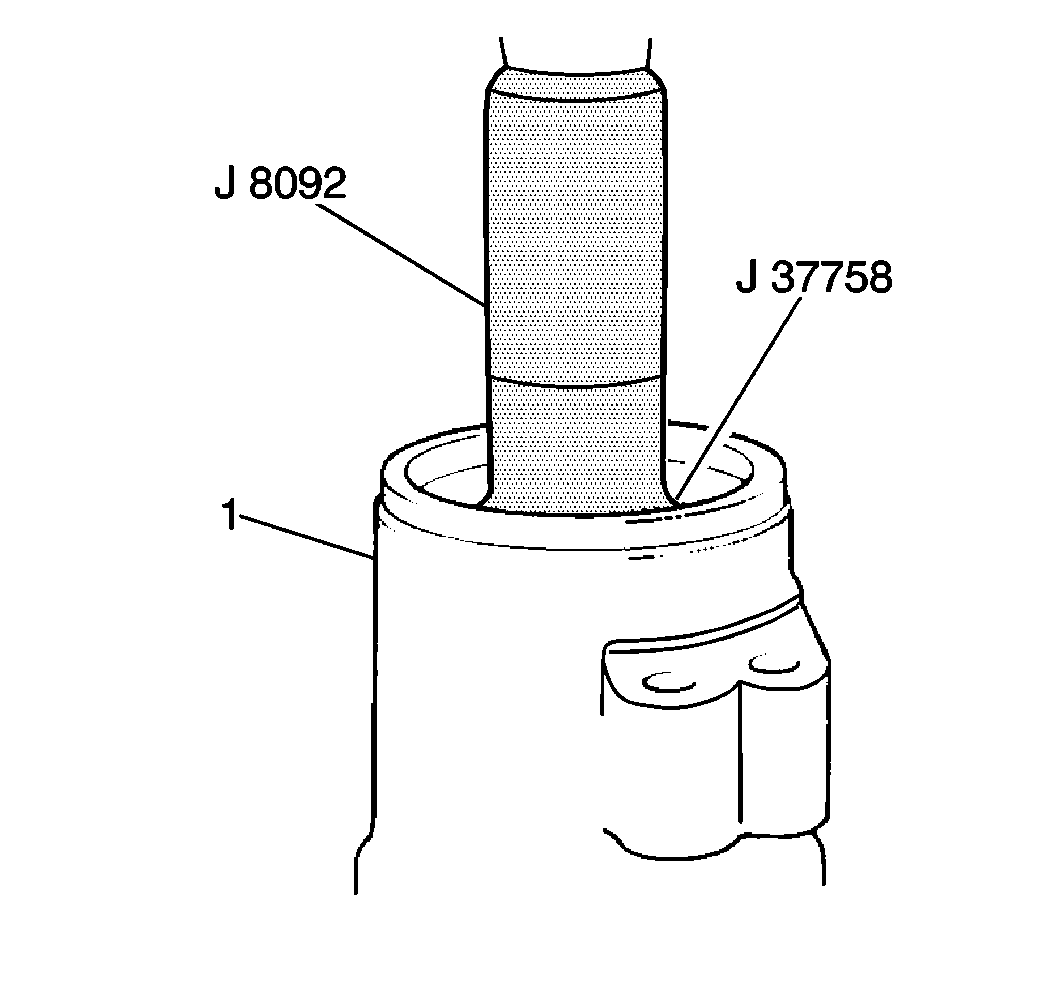
- Install the inner pinion
bearing race into the differential carrier (1) using the J 37759
with the J 8092
.
| • | Place the differential carrier on a hydraulic press and
position the inner pinion bearing race over its bore. |
| • | Use the J 37759
with the J 8092
in order
to slowly press the inner pinion bearing race evenly into
the differential carrier. |
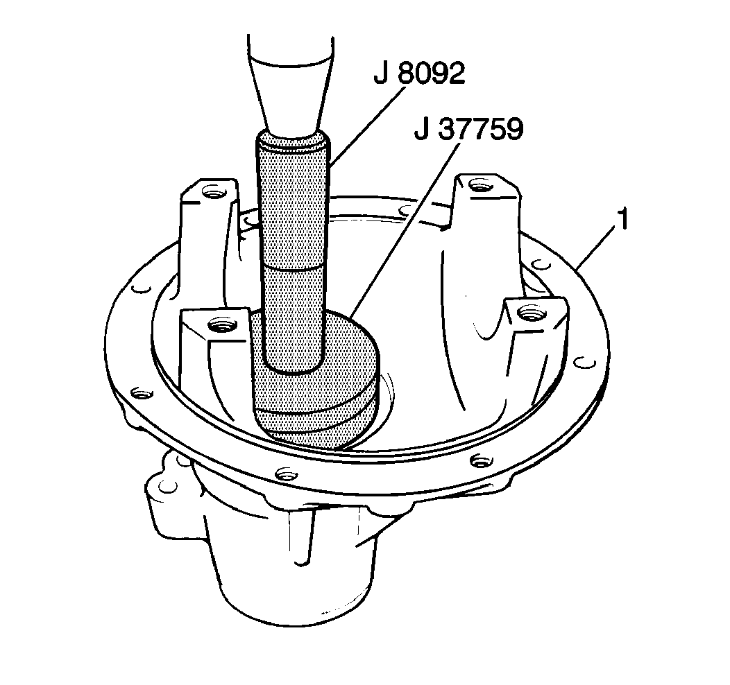
- Install the outer pinion
bearing race into the differential carrier (1) using
the J 37758
with the J 8092
.
| • | Place the differential carrier
on a hydraulic press and position the outer pinion bearing race over
its bore. |
| • | Use the J 37758
with the J 8092
, to slowly press the outer
pinion bearing race evenly into the differential carrier. |
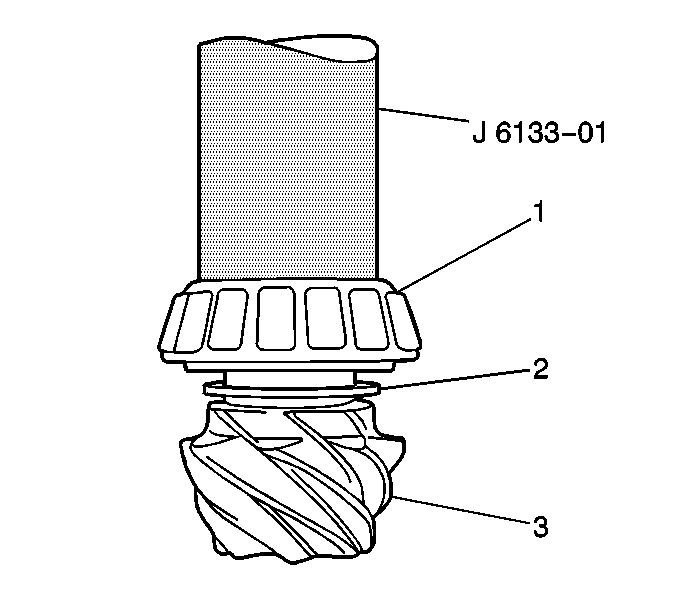
- Install a pinion selective
shim (2) onto the pinion gear shaft.
- Install the pinion bearing (1) onto the pinion gear shaft.
Use the J 6133-A
.
- Place the pinion gear (3) on a hydraulic press.
- Install the inner pinion bearing on the pinion gear shift shaft
with the tapered side facing away from the pinion gear.
- Place the J 6133-A
on the pinion gear shaft and slowly press the inner bearing into place.
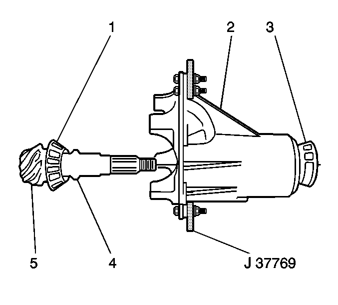
- Install a new collapsible
spacer (4) onto the pinion gear shaft with the short shank toward
the pinion gear.
- Install the outer pinion bearing (3) and the pinion gear (5)
into the differential carrier (2).
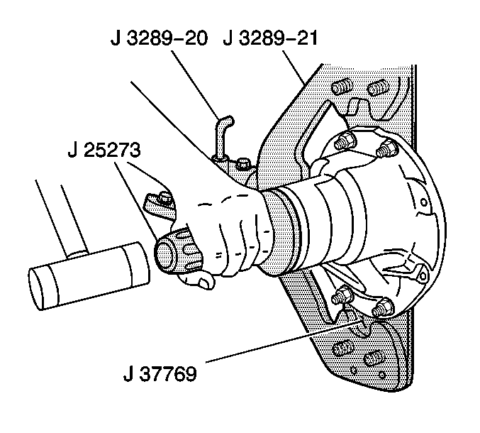
- Install a new pinion oil
seal into the differential carrier using the J 25273
.
- Apply wheel bearing lubricant GM P/N 1051344, or
equivalent, to the new pinion oil seal lip.
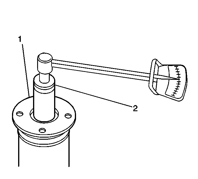
Important: Do not overtighten the pinion flange nut when adjusting the bearing
preload. Tighten the pinion flange nut gradually while taking frequent pinion
bearing preload measurements with a torque wrench. If overtightening
exists the collapsible spacer will crush requiring a new collapsible
spacer before pinion bearing preload can be properly adjusted.
- Adjust the pinion bearing preload using the J 8614-01
to hold the pinion flange stationary while tightening the
pinion flange nut.
Tighten
Tighten the nut gradually in increments of 5 N·m (44 lb in).
- Between each increments of tightening, remove the J 8614-01
, rotate the pinion gear 5 revolutions
in order to ensure pinion bearing seating and measure pinion bearing preload.
- Measure the bearing preload using a torque wrench and a 27 mm
socket (2).
- The pinion gear should require 1.2 N·m (11 lb in)
in order to rotate.
- If the pinion bearing preload is less than specified, repeat the
adjustment procedure until proper pinion bearing preload has been attained.
- Install the pinion flange nut.
- Install the side bearing
races onto the differential side bearings.
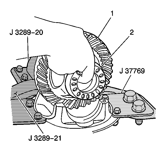
- Install the differential assembly into the differential carrier.
- Install both side bearing adjusters (2) on the side bearing
races.
- Install both side bearing caps onto differential carrier, secure
with the four side bearing cap bolts.
Tighten
Tighten differential side bearing cap bolts to 15 N·m (11 lb ft).


