Tools Required
| • | J 22912-O1 Bearing Puller |
| • | J 39200 Digital Multimeter |
| • | J 26900-5 Vernier Caliper |
Disassembly Procedure
- Remove the generator from the vehicle. Refer to Generator Replacement .
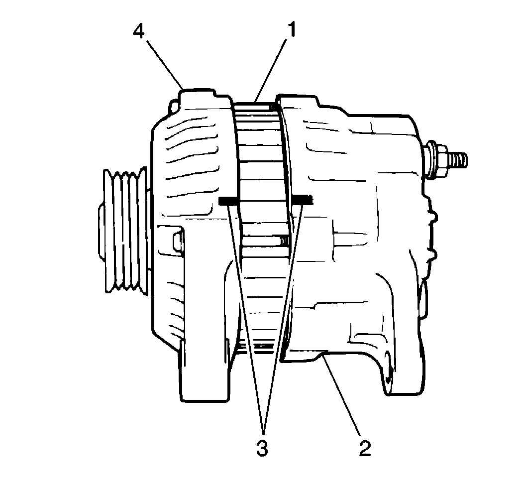
- Scribe matchmarks (3) on the front and rear housings to ensure proper assembly.
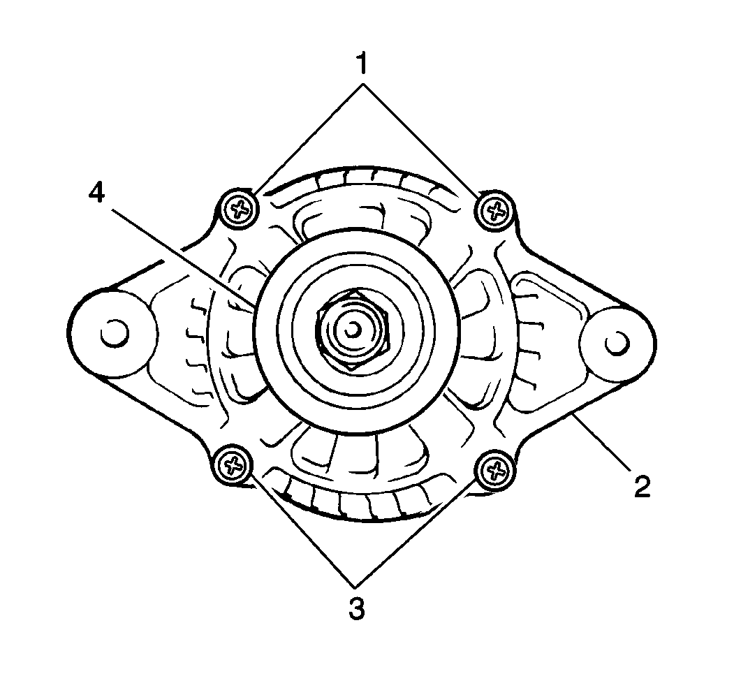
- Remove the four generator housing bolts (1, 3) from the front housing.
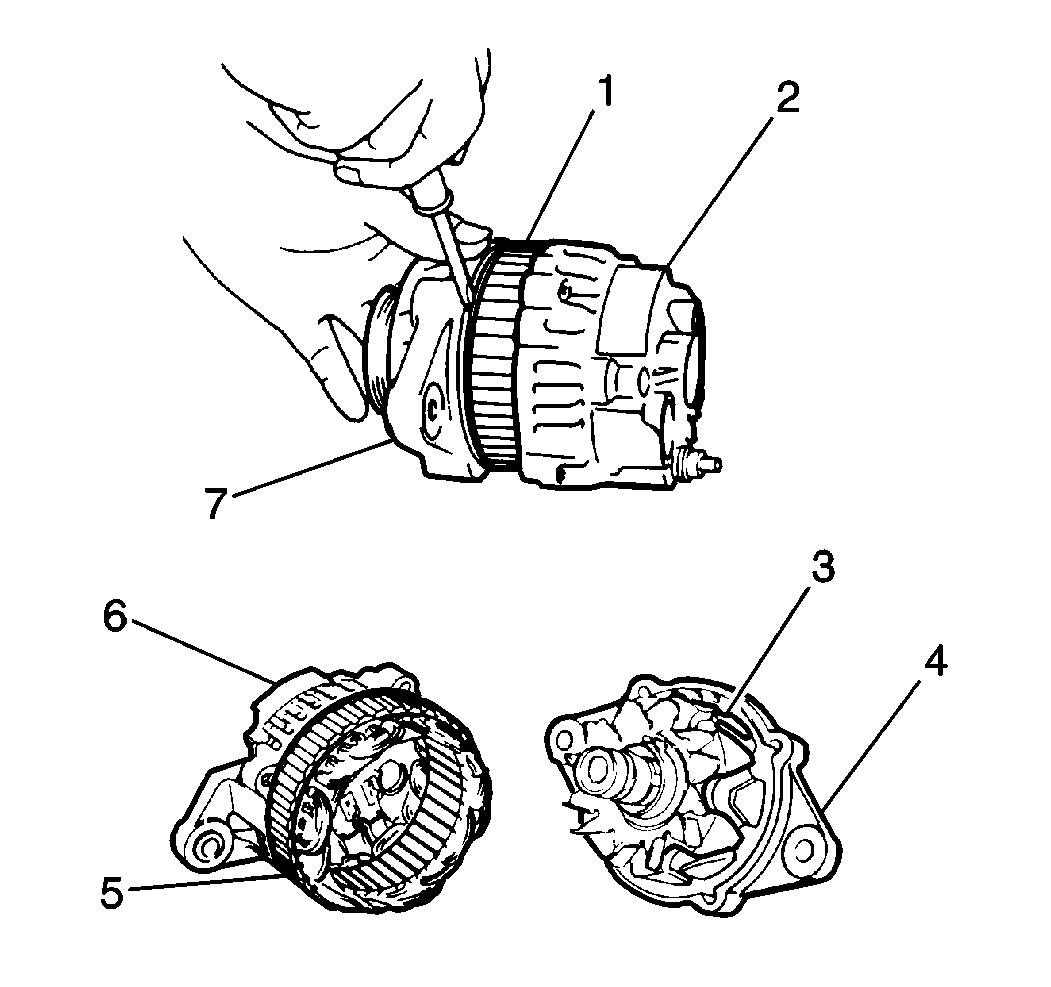
- Using a flat-bladed tool, gently pry off the front housing (7) (with the drive pulley and the rotor) from the stator coil (1) and the rear housing (2).
- Place the front housing (4) and the rotor into a vise, facing the drive pulley up.
- Remove the drive pulley retaining nut.
- Remove the drive pulley washer and the drive pulley from the rotor.
- Remove the front housing and the rotor from the vise.
- Remove the rotor and the spacer from the front housing.
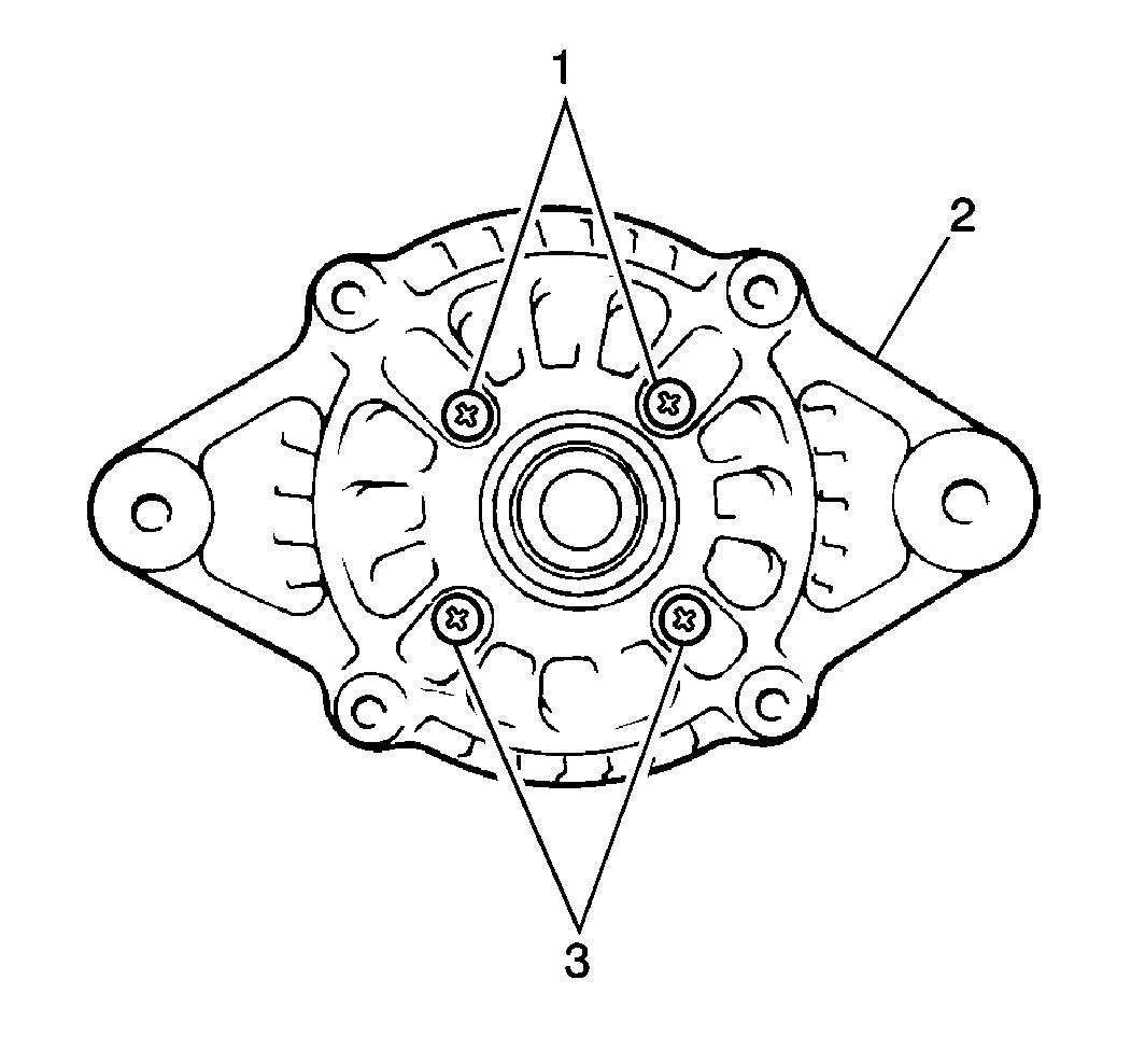
- Remove four screws (1, 3), the front bearing retainer and the front bearing from the front housing.
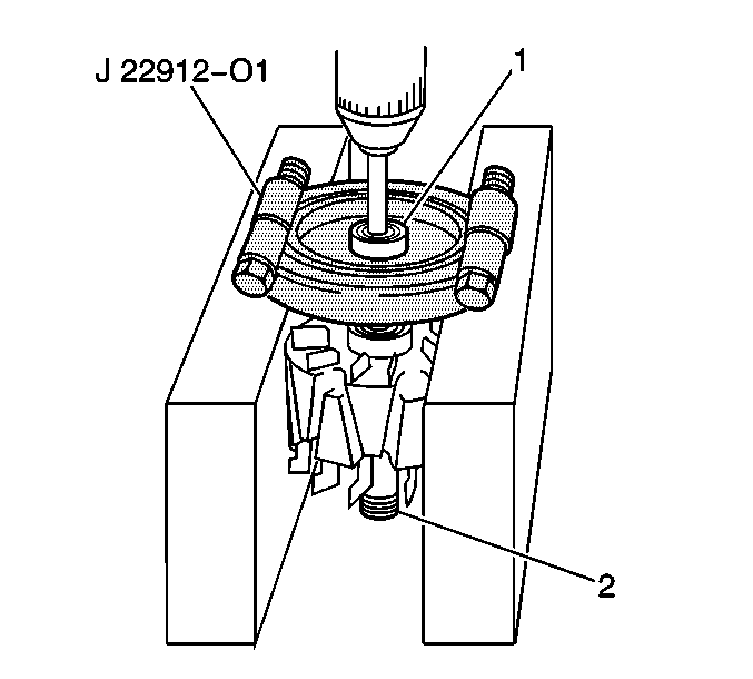
- Remove the rear bearing (1) from the rotor using a J 22912-O1 and a press.
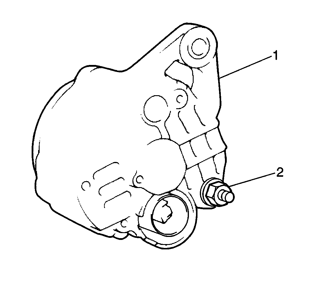
- Remove the battery terminal retaining (2) nut from the rear housing.
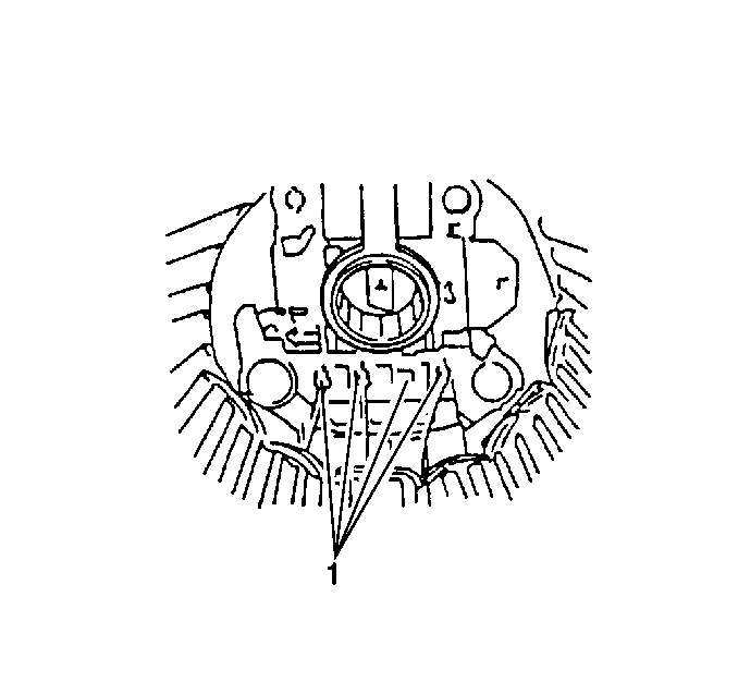
- Unsolder the stator leads (1).
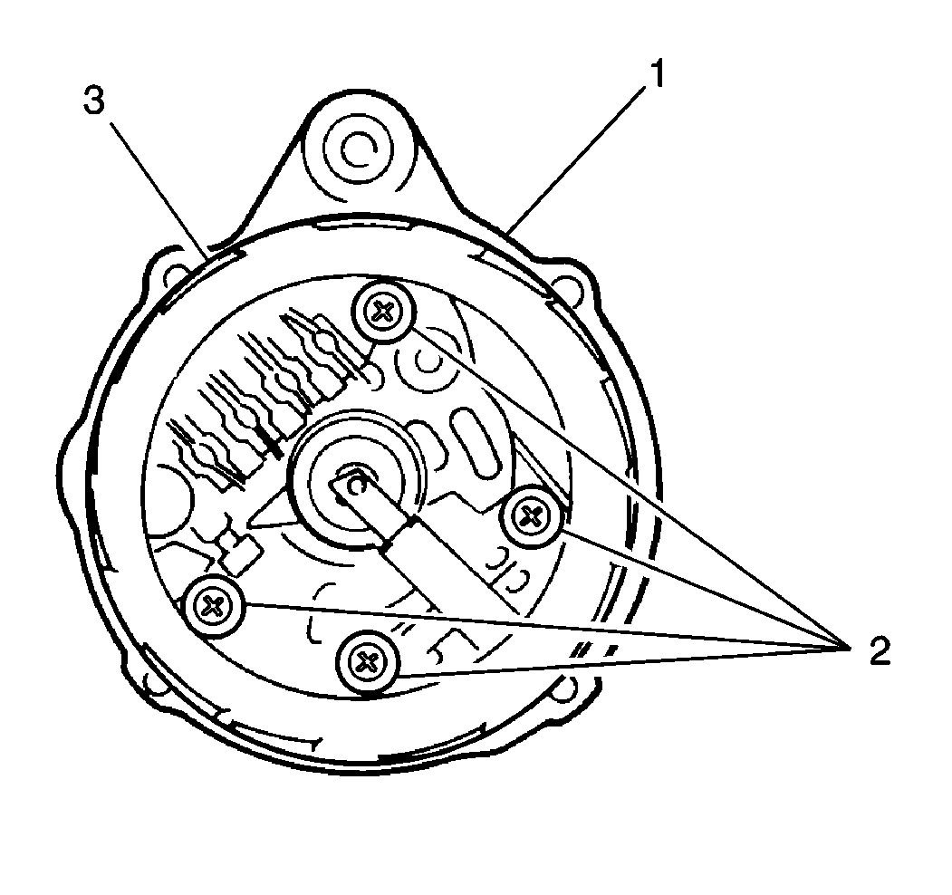
- Remove four retaining screws (2) and the stator (3) from the rear housing.
- Remove the rectifier from the rear housing.
- Remove the regulator and the brush holder from the rear housing.
- Remove the brush holder from the regulator.
- Remove the brush lead wire cover (1).
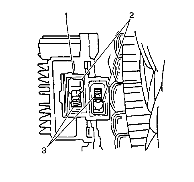
- Using a soldering iron, heat and disconnect the brush lead wires (2) from the regulator terminals.
- Remove the brushes and the brush springs (3) from the regulator.
Notice: To prevent damage to the rotor, place clean shop cloths between the rotor and the vise.
Measuring Procedure
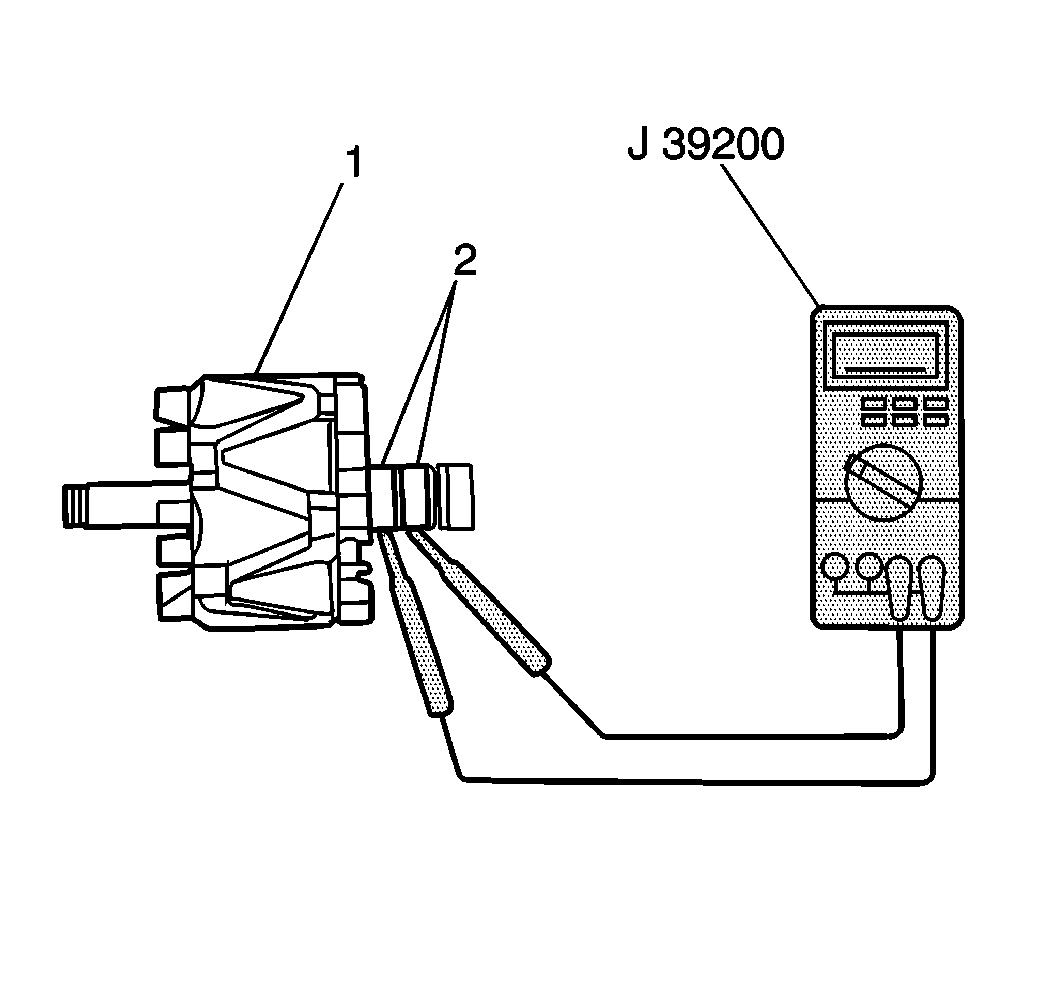
- Measure the resistance between the rotor slip rings (2) using J 39200 . If the resistance is greater than 2.5-2.9 ohms, replace the rotor.
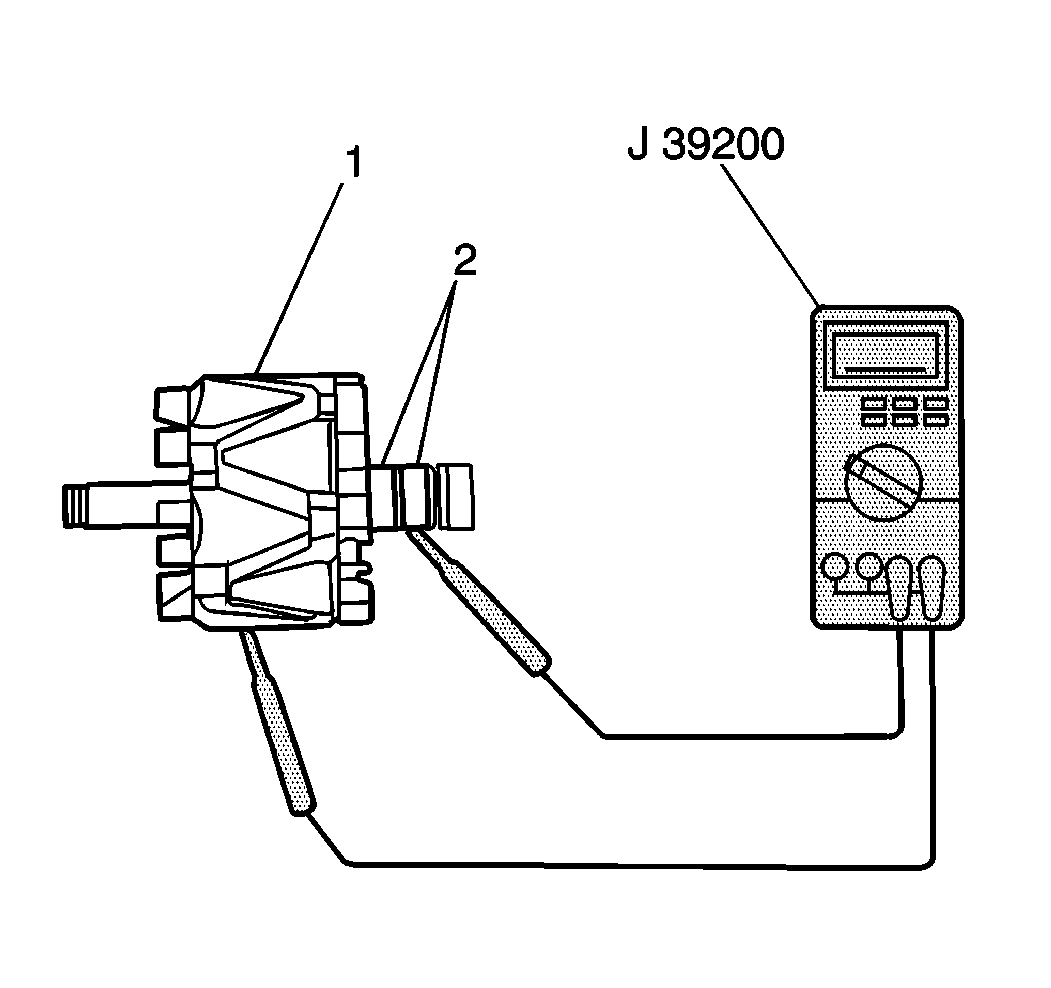
- Measure the resistance between the rotor slip rings (2) and the rotor (1) using the J 39200 . If the resistance is less than 5 ohms, replace the rotor.
- Inspect the rotor slip rings for roughness or scoring. If the slip rings are rough or scored, replace the rotor.
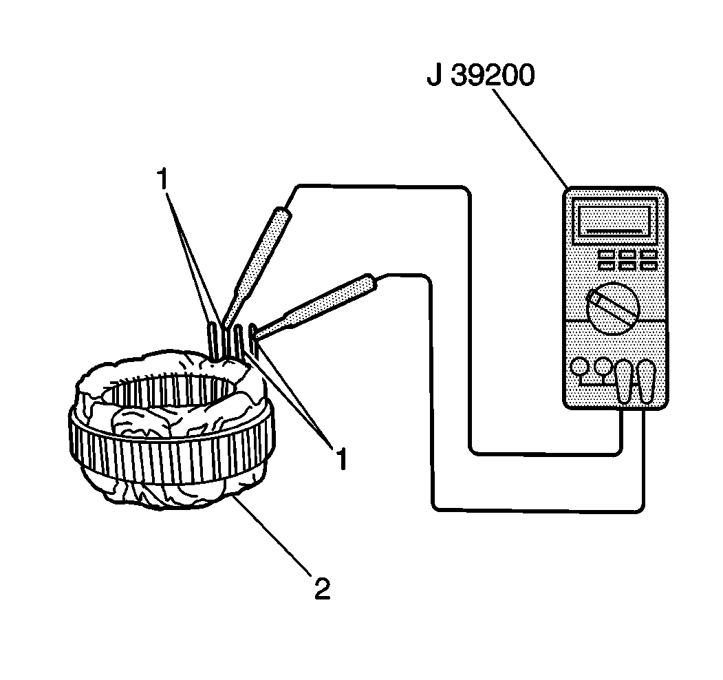
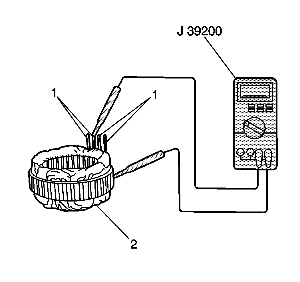
- Measure the resistance between all stator leads (1) using J 39200 . If the resistance is greater than 5 ohms for any measurement, replace the stator (2).
- Measure the resistance between all stator leads (1) and the stator core using J 39200 . If the resistance is less than 5 ohms, replace the stator (2).
- Measure the length of each brush (3) using J 26900-5 . If the brush length is less than the minimum, replace the brush.
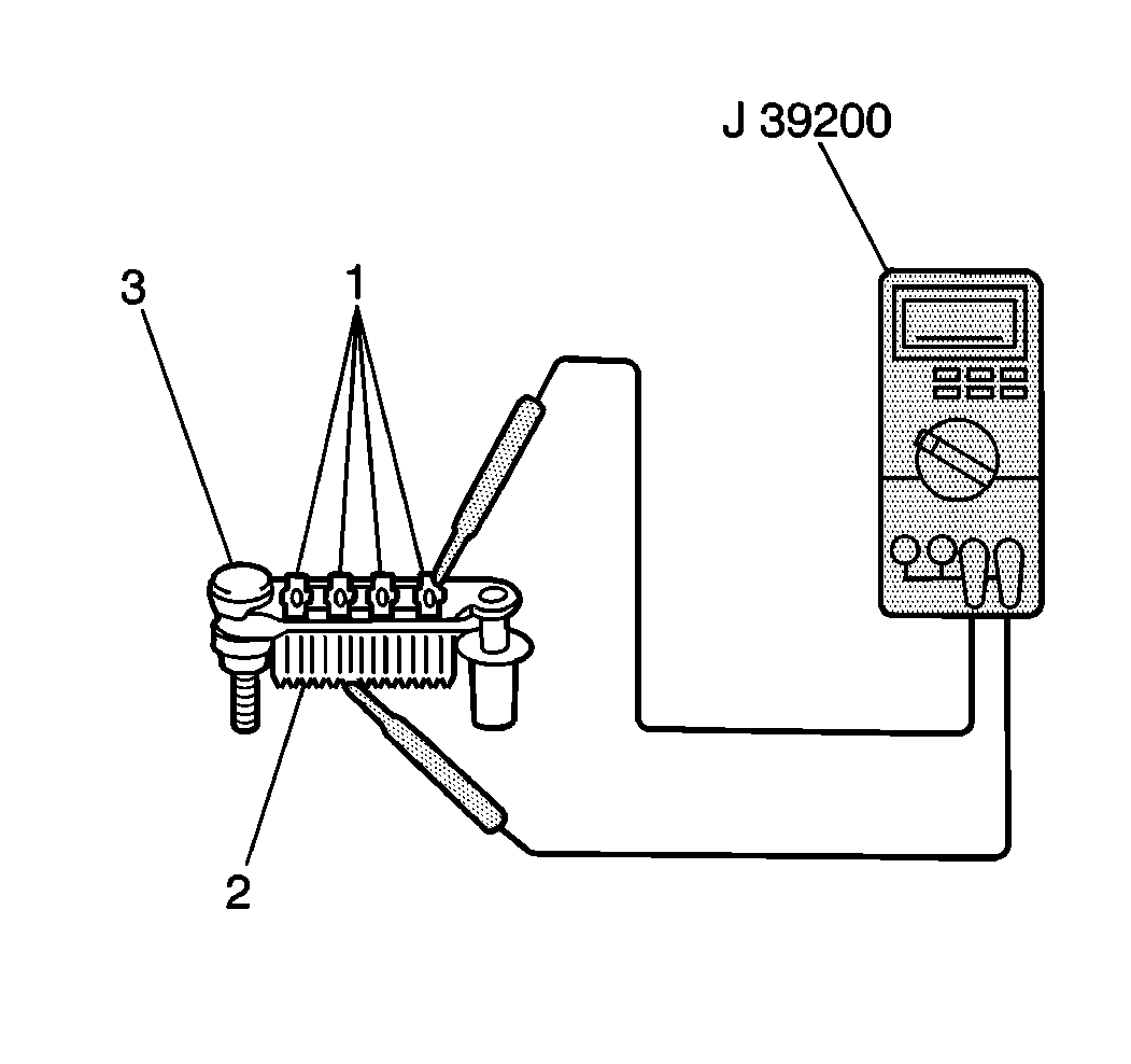
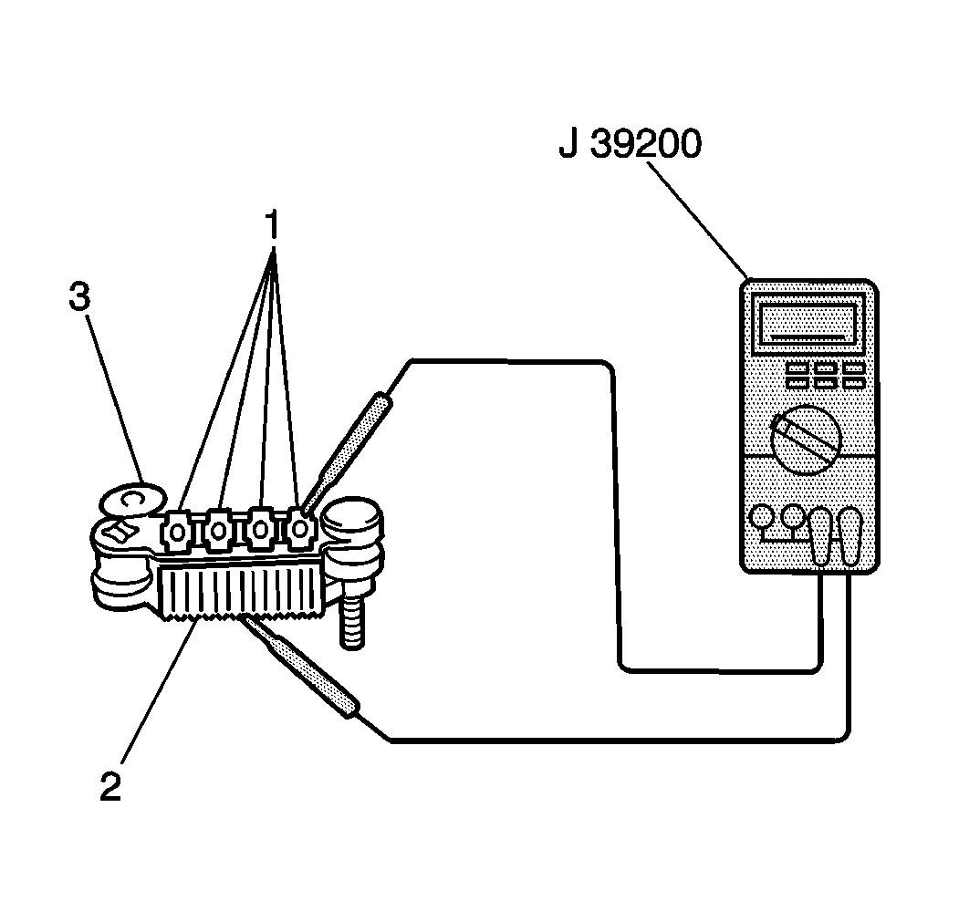
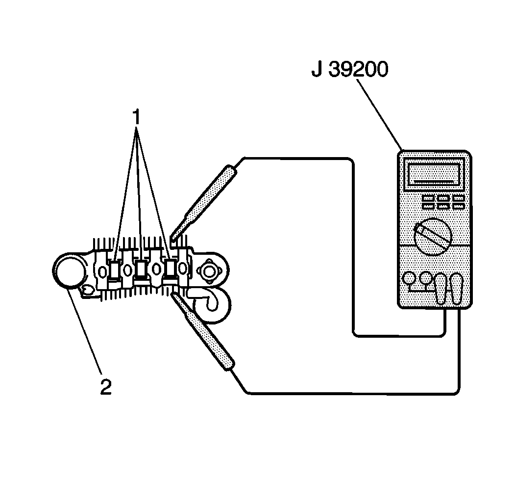
- Measure the resistance between the rectifier upper body (2) and each diode lead (1) using J 39200 . Reverse the probes and measure the resistance again. The resistance should be less than 5 ohms in one measurement and greater than 5 ohms in the other measurement. If not, replace the rectifier.
- Measure the resistance between the rectifier lower body (2) and each diode lead (1) using the J 39200 . Reverse the probes and measure the resistance again. The resistance should be less than 5 ohms in one measurement and greater than 5 ohms in the other measurement. If not, replace the rectifier.
- Measure the resistance between both leads of each rectifier diode trio (1) using the J 39200 . Reverse the probes and measure the resistance again. The resistance should be less than 5 ohms in one measurement and greater than 5 ohms in the other measurement. If not, replace the rectifier.
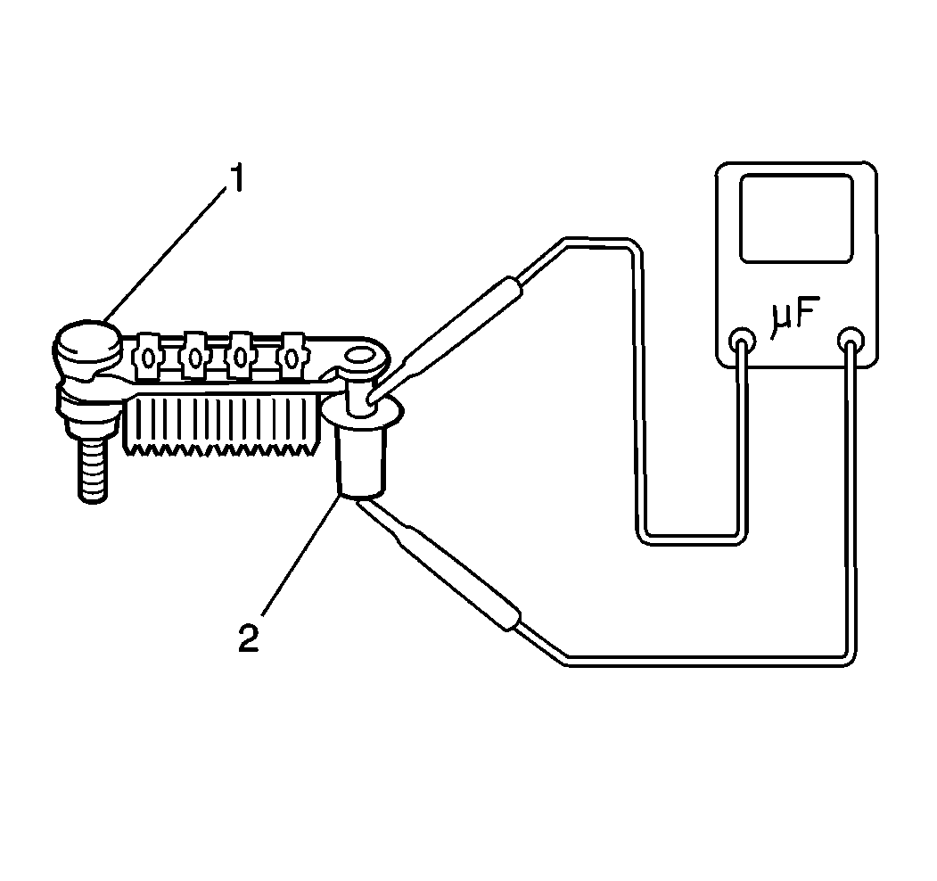
- Measure the condenser (2) capacity using a digital capacitor meter. If the condenser capacity is not 0.5 microfarads, replace the rectifier (1).
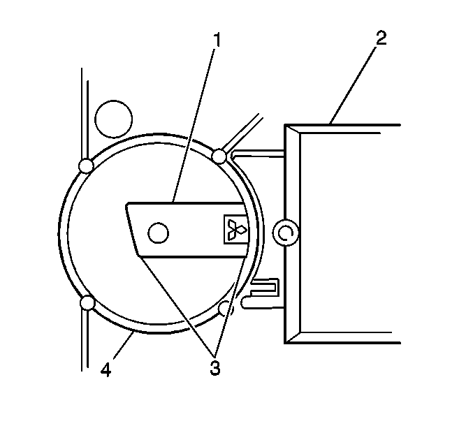
Standard Brush Length
16 mm (0.63 in)
Minimum Brush Length
2 mm (0.08 in)
Assembly Procedure
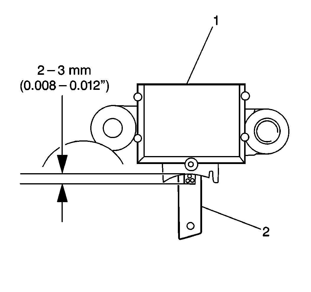
- Connect the brushes (2) to the regulator (1).
- Install the brush springs and the brushes to the regulator so that the label on each brush is 2- 3 mm (0.008-0.012 in) from the rectifier.
- Solder the brush lead wires (2) to the regulator terminals.
- Install the brush lead wire cover .
- Connect the brush holder to the regulator.
- Install the regulator and the brush holder to the rear housing.
- Install the rectifier to the rear housing.
- Install the stator to the rear housing. Secure the stator with the four retaining screws (2).
- Solder the stator lead wires (1) to the regulator terminals.
- Remove the hole plug from the rear housing.
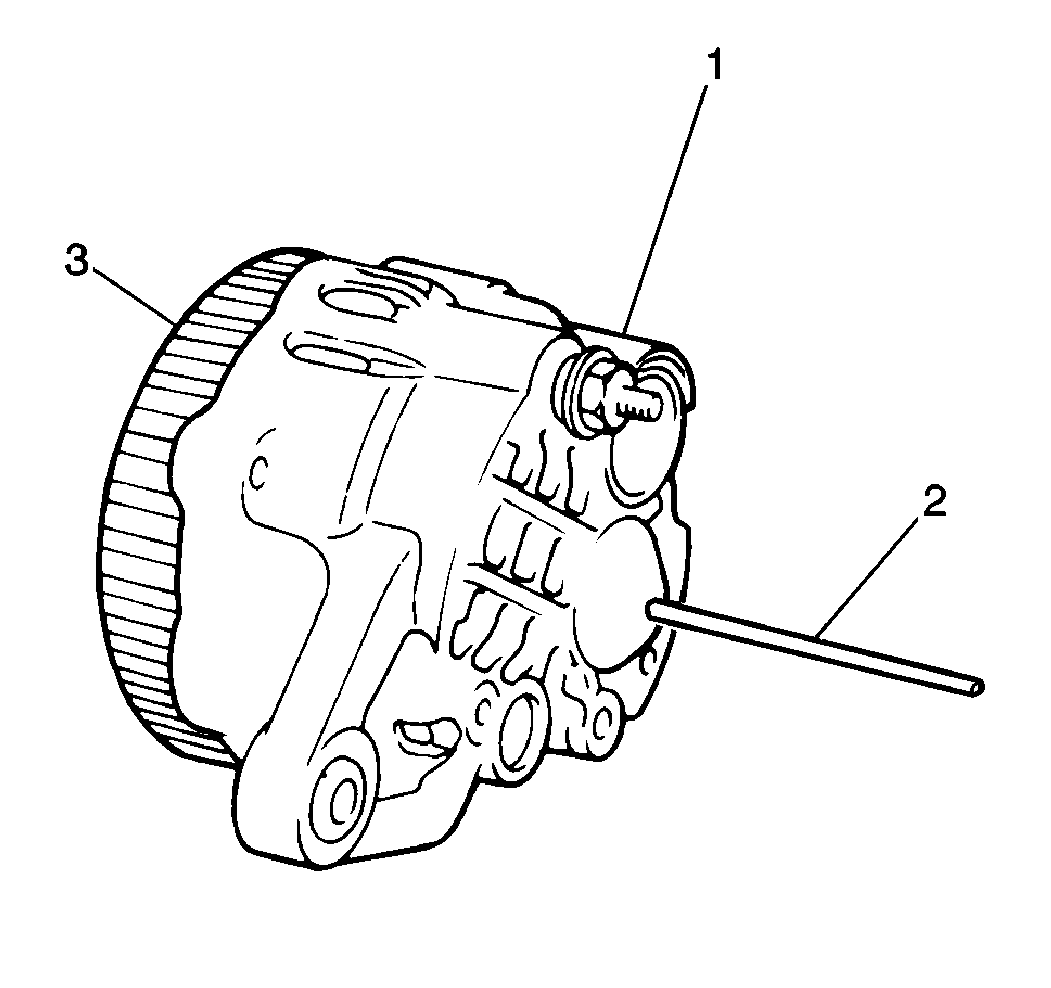
- Support the brushes with a wire inserted through the hole in the rear housing (2).
- Install the battery terminal retaining nut (2) to the rear housing.
- Install the rear bearing to the rotor.
- Install the front bearing and the front bearing retainer to the front housing. Secure with 4 screws (1,3).
- Install the rotor with the spacer to the front housing.
- Place the front housing and the rotor into a vise, facing the drive pulley end up.
- Install the drive pulley and the drive pulley washer to the rotor. Secure the pulley with the retaining nut.
- Remove the front housing and the rotor from the vise.
- Using a heat gun, heat the rear housing to 50- 60°C (122-140°F)
- Align the generator housing match marks. Install the front housing (4), with the drive pulley and rotor, to the stator coil (5) and rear housing (6).
- Install the 4 front housing generator housing bolts (1,3).
- Remove the brush support wire and install the hole plug into the rear housing.
- Make sure that the rotor rotates smoothly by turning the drive pulley.
- Install the generator to the vehicle. Refer to Generator Replacement .



Notice: Use the correct fastener in the correct location. Replacement fasteners must be the correct part number for that application. Fasteners requiring replacement or fasteners requiring the use of thread locking compound or sealant are identified in the service procedure. Do not use paints, lubricants, or corrosion inhibitors on fasteners or fastener joint surfaces unless specified. These coatings affect fastener torque and joint clamping force and may damage the fastener. Use the correct tightening sequence and specifications when installing fasteners in order to avoid damage to parts and systems.
Tighten
Tighten the battery terminal retaining nut to 10 N·m (89 lb in).


Notice: To prevent damage to the rotor, place clean shop cloths between the rotor and the vise.
Tighten
Tighten the drive pulley retaining nut to 118 N·m (86 lb ft).

Tighten
Tighten the generator housing bolts to 17 N·m (10 lb ft).
