Front Pipe Replacement 1.6L and 2.0L
Removal Procedure
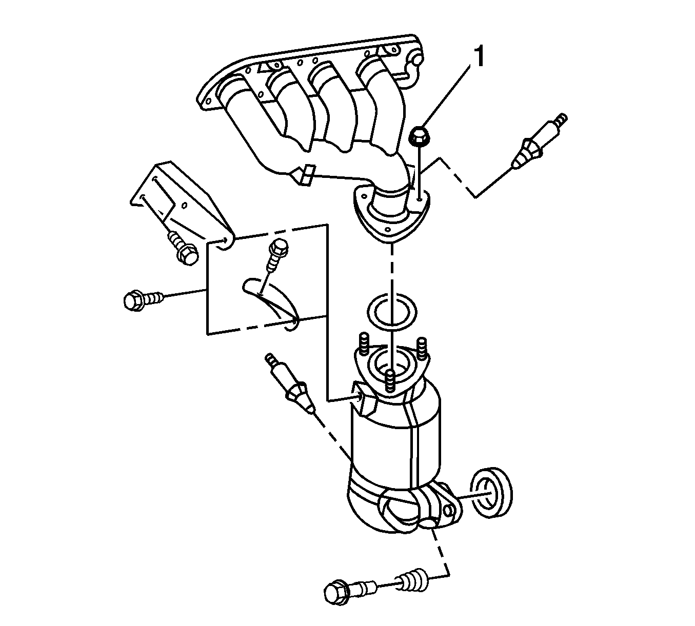
- On California 2.0L engine, remove 5 upper exhaust manifold heat shield bolts.
- Remove the upper exhaust manifold heat shield.
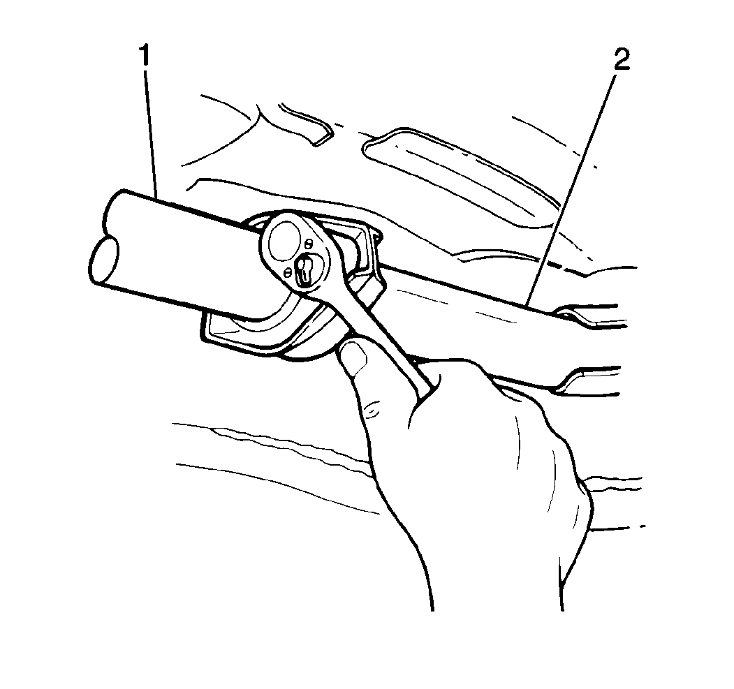
- Remove 3 exhaust manifold to front pipe nuts (1).
- On all, raise and support the vehicle. Refer to Lifting and Jacking the Vehicle in General Information.
- On California 2.0L engine, remove the heated oxygen sensor (HO2S) 2. Refer to Heated Oxygen Sensor 2 Replacement in Emission Controls.
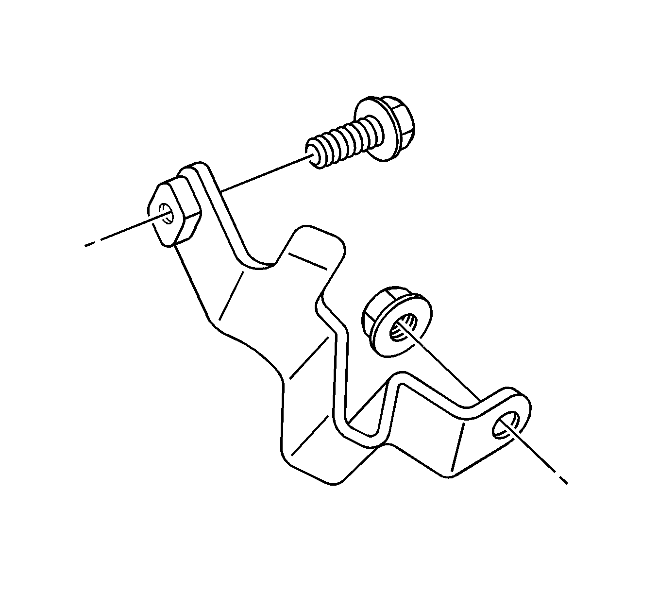
- Remove 1 bolt and 1 nut from the exhaust manifold pipe bracket.
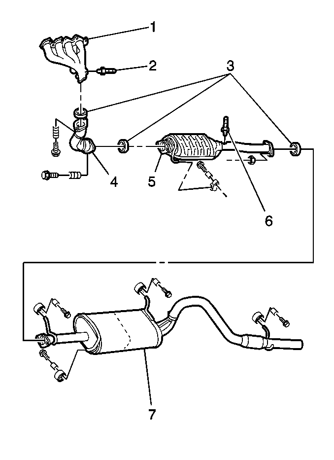
- On all, remove 2 bolts and the front pipe/TWC assembly (2) from the exhaust manifold (1).
- On 1.6L engine and non-California 2.0L engine, remove the electrical connector at the heated oxygen sensor (H02S2) (6).
- On all, remove two nuts and the front pipe/TWC assembly (1) from the resonator/muffler/tail pipe assembly.
- Remove the hanger supporting the TWC.
- Remove the front pipe/TWC assembly (1) from the vehicle.
- Clean the gasket and the seal mating surfaces.
Installation Procedure
Important: When installing a new exhaust system component, always use new gaskets and seals.
- On all, install the front pipe/TWC assembly to the vehicle.
- Support the TWC with a hanger.
- Attach the front pipe/TWC assembly with a new gasket to the resonator/muffler/tail pipe assembly.
- Secure the resonator/muffler/tail pipe assembly with 2 nuts. Do not fully tighten the nuts.
- On 1.6L engine and non-California 2.0L engine, attach the electrical connector to the heated oxygen sensor (H02S2) (6).
- On all, connect the front pipe/TWC assembly, with a new seal, to the exhaust manifold and secure with 2 bolts. Do not fully tighten the bolts.
- On California 2.0L engine, install 1 bolt and 1 nut to the exhaust manifold pipe bracket.
- Install the heated oxygen sensor (HO2S) 2. Refer to Heated Oxygen Sensor 2 Replacement in Emission Controls.
- On 1.6L engine and non-California engines, align all system components before tightening the fasteners, in order to prevent noise or vibrations.
- On California 2.0L engine, align all system components before tightening the fasteners, in order to prevent noise or vibrations.
- On all, lower the vehicle.
- On California 2.0L engine, install 3 exhaust manifold to front pipe nuts (1).
- Position exhaust manifold upper heat shield to the exhaust manifold.
- Install 5 exhaust manifold upper heat shield bolts.

Notice: Refer to Fastener Notice in the Preface section.

Tighten
Tighten the front exhaust pipe bracket nut and bolt to 50 N·m (37 lb ft).
Tighten
| • | Tighten the front pipe/TWC assembly-to-exhaust manifold bolts to 50 N·m (37 lb ft). |
| • | Tighten the front pipe/TWC assembly-to-resonator/muffler/tail pipe assembly nuts to 35 N·m (26 lb ft). |
Tighten
Tighten the front pipe/TWC assembly-to-resonator/muffler/tail pipe assembly
nuts to 35 N·m (26 lb ft).

Tighten
Tighten the front pipe assembly-to-exhaust manifold bolts to 50 N·m
(37 lb ft).
Front Pipe Replacement 2.5L
Removal Procedure
- Disconnect the Heated Oxygen Sensor (HO2S1) electrical connectors and detach the couplers from the coupler mounting bracket.
- Raise and support the vehicle. Refer to Lifting and Jacking the Vehicle in General Information.
- Remove the propeller shaft. Refer to Front Propeller Shaft Replacement .
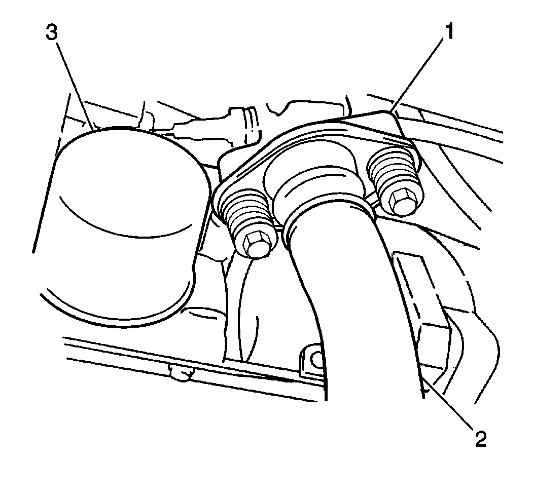
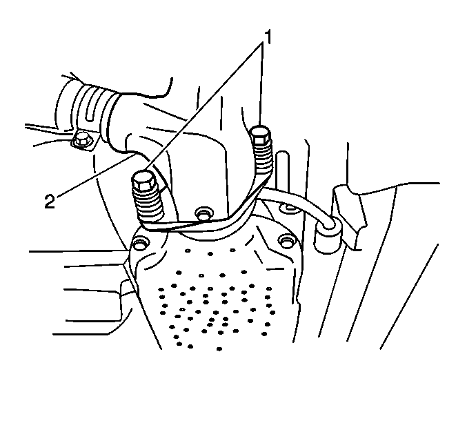
- Remove the 2 bolts (1) from the front pipe assembly (2).
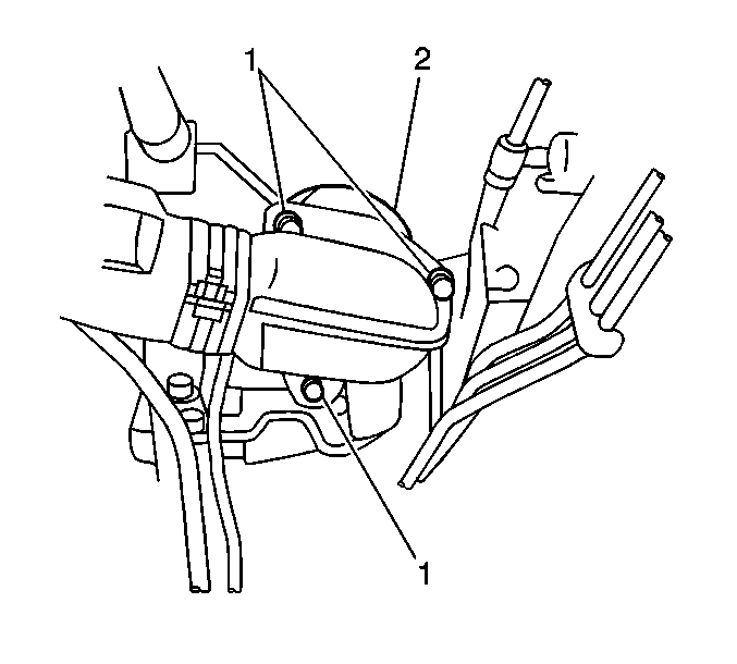
- Remove the 6 front pipe nuts (1) from the exhaust manifolds (2).
- Remove the front pipe and the exhaust manifold gaskets.
Installation Procedure
- Position the front pipe with new exhaust manifold gaskets.
- Install the 6 front pipe nuts (1) to the exhaust manifolds (2). Do not fully tighten the nuts.
- Install the 2 bolts (1) to the front pipe assembly (2). Do not fully tighten the bolts.
- Install the propeller shaft. Refer to Front Propeller Shaft Replacement .
- Align all system components before tightening the fasteners, in order to prevent noise or vibrations.
- Tighten the front pipe assembly bolts.
- Tighten the front pipe assembly nuts.
- Lower the vehicle.
- Connect the Heated Oxygen Sensor (HO2S1) electrical connectors and attach the couplers to the coupler mounting bracket.
Important: When installing a new exhaust system component, always use new gaskets and seals.


Notice: Use the correct fastener in the correct location. Replacement fasteners must be the correct part number for that application. Fasteners requiring replacement or fasteners requiring the use of thread locking compound or sealant are identified in the service procedure. Do not use paints, lubricants, or corrosion inhibitors on fasteners or fastener joint surfaces unless specified. These coatings affect fastener torque and joint clamping force and may damage the fastener. Use the correct tightening sequence and specifications when installing fasteners in order to avoid damage to parts and systems.
Tighten
Tighten the front pipe assembly bolts to 50 N·m
(37 lb ft).
Tighten
Tighten the front pipe assembly nuts to 50 N·m
(37 lb ft).
