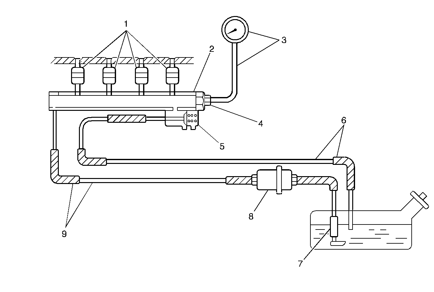
The fuel pressure regulator
is a diaphragm-operated pressure relief valve consisting of a diaphragm (3),
a spring (2), and a valve (4). The fuel pressure regulator
keeps the fuel pressure applied to the fuel injector at a
pressure much more than the pressure in the intake manifold.
The pressure applied to chamber A (2) of the fuel pressure regulator
is the intake manifold pressure. The pressure applied to chamber B (5) of
the fuel pressure regulator is fuel pressure. When the fuel
pressure rises at least 210 kPa (30 psi) higher
than the intake manifold pressure, the fuel pushes a valve
in the regulator open and excess fuel (6) returns to the fuel
tank via the fuel return pipe.
The fuel feed, return pipes and hoses carry the fuel from the fuel tank
to the fuel injectors and back to the fuel tank. These pipes and hoses
are attached to the chassis of the
vehicle, and should be inspected periodically
for kinks or dents that may restrict the fuel flow.
The fuel vapor pipe and hoses carry the fuel vapors from the fuel tank
to the evaporative emission canister located in the engine compartment. The
fuel vapors are stored in the canister
when the engine is not running. When
the engine is running at the normal operating temperature
and the accelerator pedal is depressed,
the powertrain control module (PCM) will command the evaporative
emission canister purge valve to
open and allow the stored fuel vapors to
be purged into the intake manifold where they will be
burned in the combustion process.
The accelerator control system is cable-operated. When the accelerator
pedal is depressed, the cable pulls the throttle lever open, increasing the
throttle plate opening. When the accelerator pedal is released,
the throttle lever spring pressure returns the throttle lever to
the idle position, decreasing the throttle plate opening.
The function of the fuel metering system is deliver the correct amount
of fuel to the engine under all operating conditions. Fuel is delivered
to each cylinder by the fuel injectors. The fuel injectors are
controlled sequentially by the powertrain control module (PCM). The
PCM bases the control of the fuel injectors on several important
engine parameters. These engine parameters include the following:
The two most important inputs for fuel control are the mass air flow
(MAF) sensor and the heated oxygen sensor 1 (HO2S 1). The MAF sensor provides
the powertrain control module (PCM) with engine air intake quantity,
while the HO2S 1 provides the PCM with exhaust stream oxygen content
information. Determining air density is critical to proper air/fuel
management. Air density is primarily derived from the MAF sensor input.
The MAF sensor measures the air volume and determines the air density.
Larger volumes of air and denser air masses require additional
fuel. The information from the MAF sensor is used by the PCM in
order to modify the fuel injector pulse width.
The PCM modifies the air/fuel mixture by changing the injector pulse
width signal sent to the injectors. By constantly measuring the air intake
and the exhaust oxygen content and adjusting the injector pulse
width, the air fuel ratio is kept very close to the optimal 14.7:1.
This is the range at which the three-way catalytic converter (TWC)
operates most effectively and at which the emissions of this vehicle
are kept to a minimum. The constant tailoring of the air/fuel ratio
is based upon feedback from the HO2S 1 and is referred to as closed
loop operation.

