Removal Procedure

- Raise and support the vehicle. Refer
to
Lifting and Jacking the Vehicle
in General Information.
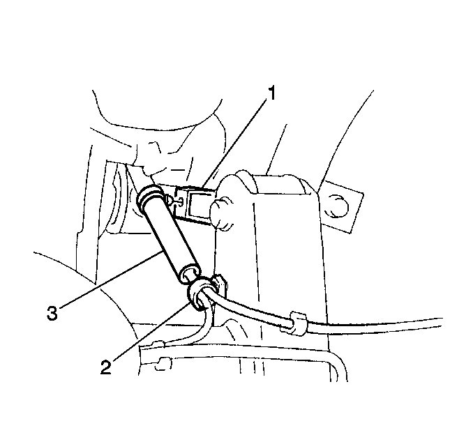
- If the vehicle is equipped with ABS, disconnect the wheel speed
sensor clamp (2) from the left upper control arm (1).
Important: Note the location and the position of the fasteners in order to aid
the installation of the component.
- Remove the following components:
Installation Procedure

Important:
| • | Install the fasteners in the original location and position. |
| • | DO NOT tighten the fasteners before lowering the vehicle. The weight
of the vehicle must be on the tires and wheels before tightening the fasteners. |
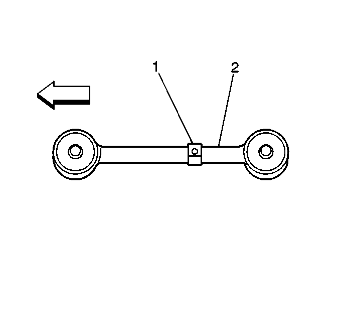
| • | If the vehicle has ABS, the front of the upper control arm must be
toward the front of the vehicle. |
- Install the following components to the frame:
| • | The upper control arm (2) |
- Install the following components to the axle housing:
- If the vehicle has ABS, connect the wheel speed sensor harness
clamp (1) to the upper control arm.
- Lower the vehicle.
Notice: Refer to Fastener Notice in the Preface section.
- With the weight of the vehicle on the tires and wheels, tighten the
nuts and the bolts.
Tighten
Tighten the nuts and the bolts to 100 N·m (73.8 lb ft).


