Steering Knuckle Replacement 4WD
Tools Required
| • | J 6627-A Tie Rod Puller |
| • | J 43631 Ball Joint Remover |
Removal Procedure
- Raise and support the vehicle. Refer to Lifting and Jacking the Vehicle in General Information.
- Remove the tire and wheel assembly. Refer to Tire and Wheel Removal and Installation in Tires and Wheels.
- Remove the brake rotor. Refer to Brake Rotor Replacement in Disc Brakes.
- Remove the hub with the bearings and the seals . Refer to Front Wheel Hub, Bearing, and Seal Replacement .
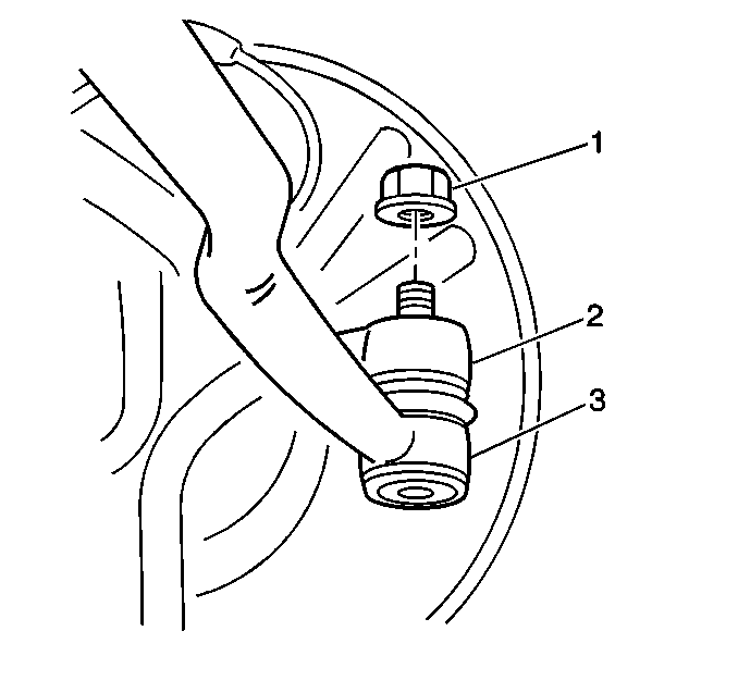
- Remove the tie rod nut (1).
- Use the J 6627-A , or equivalent, in order to separate the outer tie rod (3) from the knuckle (2).
- Remove the 4 bolts from the brake shield.
- Remove the brake shield from the spindle.
- Remove the spindle with the drive shaft bearing from the knuckle.
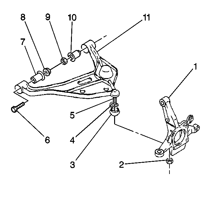
- Remove the nut (2) from the control arm ball stud (5).
- Support the lower control arm (11) with a jack.
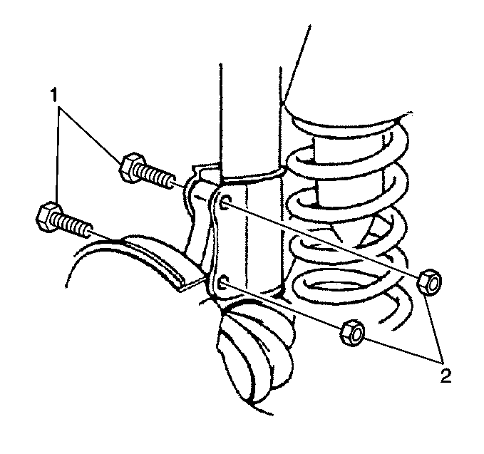
- Remove the 2 nuts (2) and the 2 bolts (1) from the strut bracket.
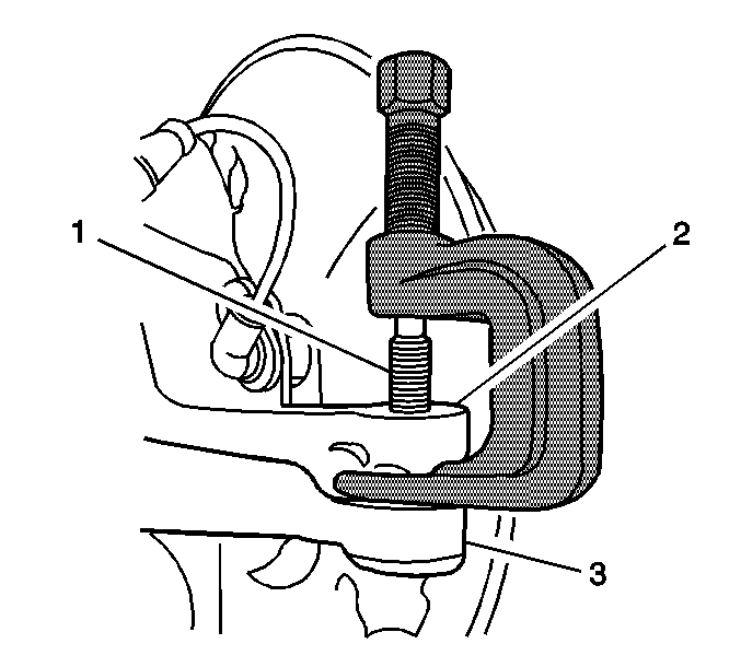
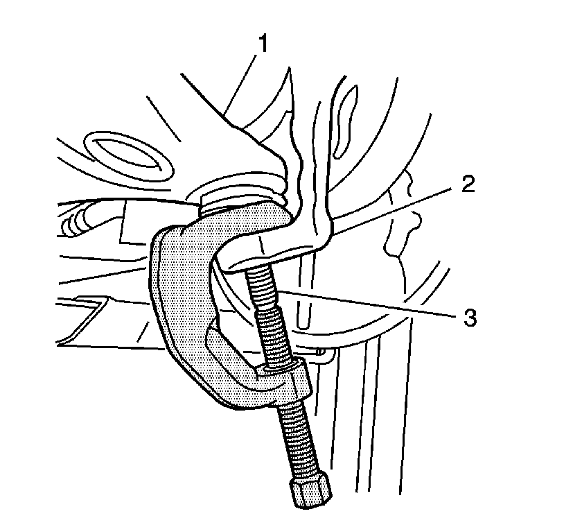
- Use the J 43631 , or equivalent, in order to remove the knuckle (2) from the ball stud (3).
- Remove the front drive shaft outer seal from the knuckle.
- Remove the front drive shaft inner seal from the knuckle.
Caution: To prevent personal injury and/or component damage, use the proper tools to support the lower control arm when removing the coil spring. The coil spring is under extreme pressure and can become a projectile should the spring separate from the lower control arm before all of the tension is relieved.
Installation Procedure
- Apply wheel bearing lubricant, GM P/N 1051344 (Canadian P/N 993037) or equivalent, to the inner seal lip and to the inner seal hollow. Verify the lubricant fills more than 60 percent of the vacant space.
- Install the drive shaft inner seal to the knuckle. Verify the seal contacts the stepped surface of the knuckle.
- Apply wheel bearing lubricant, GM P/N 1051344 (Canadian P/N 993037) or equivalent, to the outer seal lip and to the inner seal hollow. Verify the lubricant fills more than 60 percent of the vacant space.
- Install the drive shaft outer seal to the knuckle.
- Install the knuckle (1) to the ball stud (5).
- Support the lower control arm (11) with a jack.
- Install the 2 nuts (2) and the 2 bolts (1) to the strut bracket.
- Remove the jack from the lower control arm.
- Install a NEW nut to the lower control arm ball stud.
- Install the tie rod (3) to the knuckle (2).
- Install a NEW tie rod nut (1).
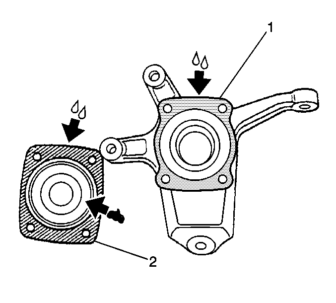
- Coat the wheel spindle mating surface (2) and the wheel knuckle mating surface (1) with General Motors Sealer, GM P/N 12378478 (Canadian P/N 88900041) or equivalent.
- Fill the recess in the wheel spindle (2) with 10 g (0.4 oz) of wheel bearing lubricant, GM P/N 1051344 (Canadian P/N 993037) or equivalent.
- Install the wheel spindle (2) to the knuckle (1).
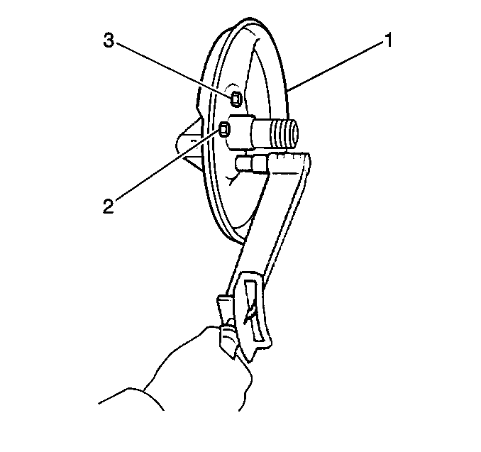
- Install the brake shield (1) to the spindle.
- Install the 4 bolts to the brake shield.
- Install the wheel hub, the bearings, and the seals. Refer to Front Wheel Hub, Bearing, and Seal Replacement .
- Install the brake rotor. Refer to Brake Rotor Replacement in Disc Brakes.
- Install the tire and wheel assembly. Refer to Tire and Wheel Removal and Installation in Tires and Wheels.
- Lower the vehicle.
- Measure the wheel alignment. Adjust the alignment if necessary. Refer to Wheel Alignment Measurement in Wheel Alignment.

Notice: Refer to Fastener Notice in the Preface section.

Tighten
Tighten the nuts and the bolts to 95 N·m (70.1 lb ft).
Tighten
Tighten the nut to 60 N·m (43.5 lb ft).

Tighten
Tighten the nut to 43 N·m (31.5 lb ft).
Tighten
Tighten the bolts to 50 N·m (36.5 lb ft).
Steering Knuckle Replacement 2WD
Tools Required
| • | J 6627-A Tie Rod Puller |
| • | J 43631 Ball Joint Remover |
Removal Procedure
- Raise and support the vehicle. Refer to Lifting and Jacking the Vehicle in General Information.
- Remove the tire and wheel assembly. Refer to Tire and Wheel Removal and Installation in Tires and Wheels.
- Remove the brake rotor. Refer to Brake Rotor Replacement in Disc Brakes.
- Remove the hub with the bearings and the seals. Refer to Front Wheel Hub, Bearing, and Seal Replacement .
- Remove the tie rod nut (1).
- Use the J 6627-A , or equivalent, in order to separate the outer tie rod (3) from the knuckle (2).
- Remove the 4 bolts from the brake shield.
- Remove the brake shield from the spindle.
- Remove the spindle from the knuckle.
- Remove the nut (2) from the control arm ball stud (5).
- Support the lower control arm (11) with a jack.
- Remove the 2 nuts (2) and the 2 bolts (1) from the strut bracket.
- Use the J 43631 , or the equivalent, in order to remove the knuckle (2) from the ball stud (3).
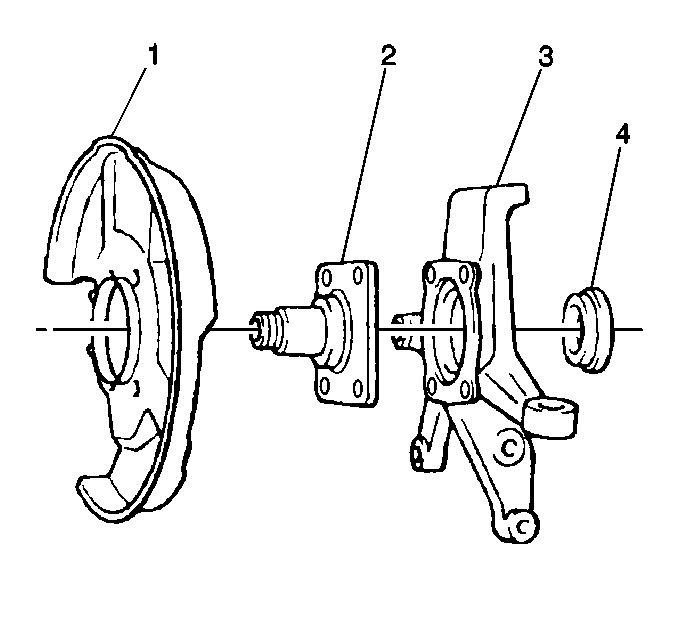
- Remove the knuckle cap (4) from the knuckle (3).


Caution: To prevent personal injury and/or component damage, use the proper tools to support the lower control arm when removing the coil spring. The coil spring is under extreme pressure and can become a projectile should the spring separate from the lower control arm before all of the tension is relieved.


Installation Procedure
- Clean the knuckle cap (4) and the knuckle (3).
- Coat the knuckle cap mating surface and the wheel knuckle mating surface with General Motors Sealer, GM P/N 12378478 (Canadian P/N 88900041) or equivalent.
- Install the knuckle cap to the knuckle.
- Install the knuckle (1) to the ball stud (5).
- Support the lower control arm (11) with a jack.
- Install the 2 nuts (2) and the 2 bolts (1) to the strut bracket.
- Install a NEW nut to the lower control arm ball stud.
- Remove the jack from the lower control arm.
- Install the tie rod (3) to the knuckle (2).
- Install a NEW tie rod nut (1).
- Coat the wheel spindle mating surface (2) and the wheel knuckle mating surface (1) with General Motors Sealer, GM P/N 12378478 (Canadian P/N 88900041) or equivalent.
- Fill the recess in the wheel spindle (2) with 10 g (0.4 oz) of wheel bearing lubricant, GM P/N 1051344 (Canadian P/N 993037) or equivalent.
- Install the wheel spindle (2) to the knuckle (1).
- Install the brake shield (1) to the spindle.
- Install the 4 bolts to the brake shield.
- Install the wheel hub, the bearings, and the seals. Refer to Front Wheel Hub, Bearing, and Seal Replacement .
- Install the brake rotor. Refer to Brake Rotor Replacement in Disc Brakes.
- Install the tire and wheel assembly. Refer to Tire and Wheel Removal and Installation in Tires and Wheels.
- Lower the vehicle.
- Measure the wheel alignment. Adjust the alignment if necessary. Refer to Wheel Alignment Measurement in Wheel Alignment.


Notice: Use the correct fastener in the correct location. Replacement fasteners must be the correct part number for that application. Fasteners requiring replacement or fasteners requiring the use of thread locking compound or sealant are identified in the service procedure. Do not use paints, lubricants, or corrosion inhibitors on fasteners or fastener joint surfaces unless specified. These coatings affect fastener torque and joint clamping force and may damage the fastener. Use the correct tightening sequence and specifications when installing fasteners in order to avoid damage to parts and systems.
Tighten
Tighten the nuts and the bolts to 95 N·m (70.1 lb ft).
Tighten
Tighten the nut to 60 N·m (43.5 lb ft).

Tighten
Tighten the nut to 43 N·m (31.5 lb ft).


Tighten
Tighten the bolts to 50 N·m (36.5 lb ft).
