Tools Required
J 45531 Halfshaft Removal Tool
Removal Procedure
- Raise and Support the vehicle. Refer to Lifting and Jacking the Vehicle in General Information.
- Remove the following components, if the vehicle is equipped:
- Remove the right front tire and wheel assembly. Refer to Tire and Wheel Removal and Installation in Tires and Wheels.
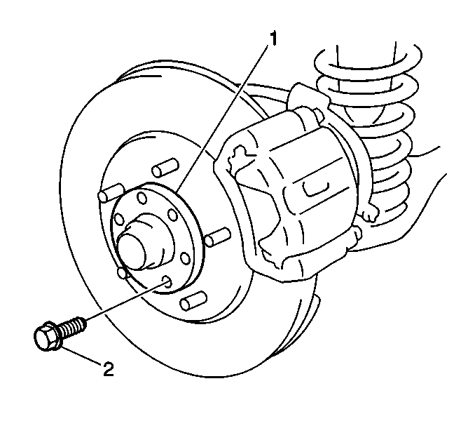
- Remove the 6 bolts (2) and the flange (1).
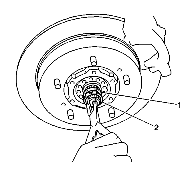
- Remove the right drive axle shaft snap ring (1).
- Remove the right drive axle shaft spindle washer (1) from the drive axle shaft.
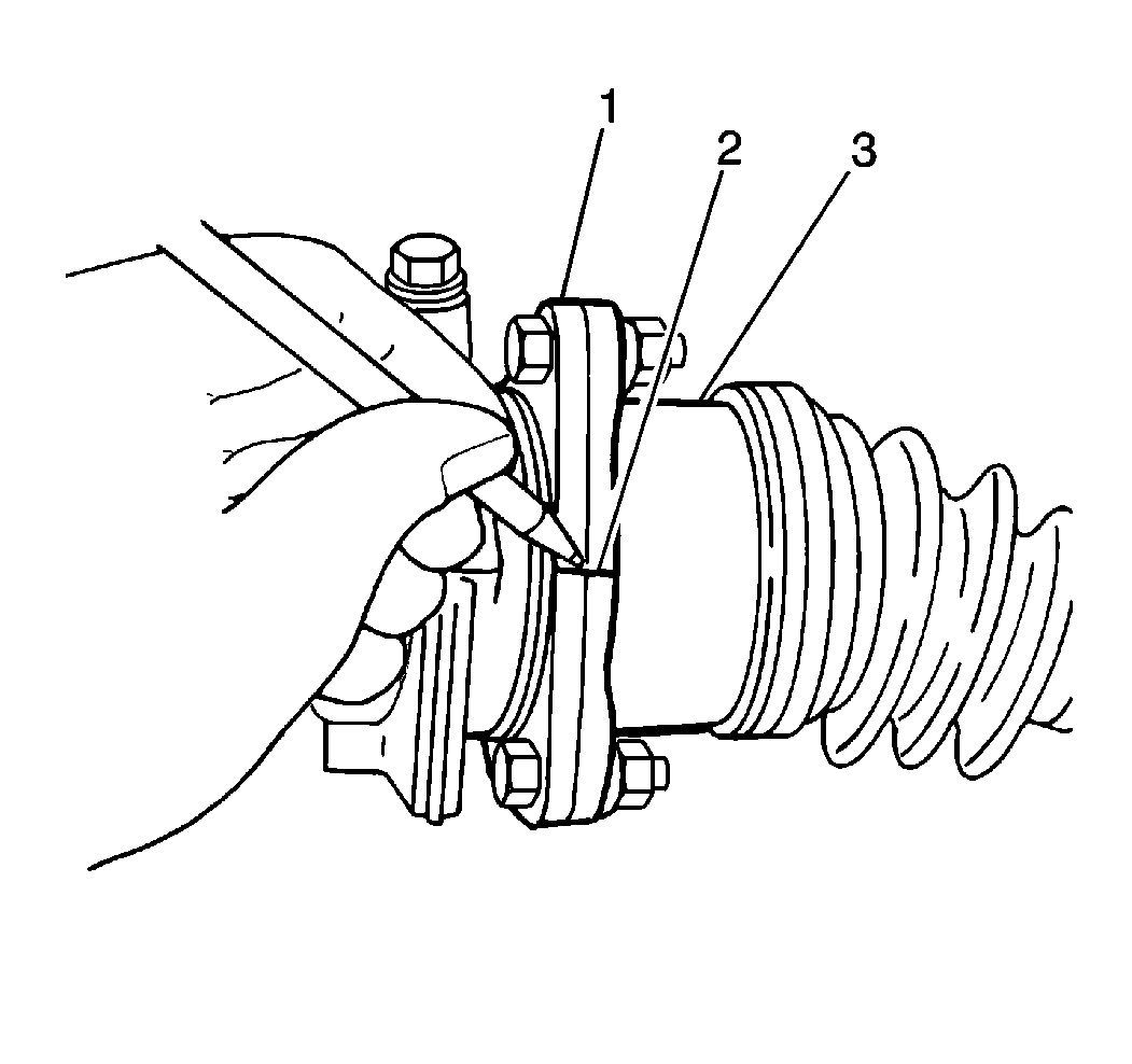
- Make a reference mark (2) on the left drive axle mating flanges (1) and (3).
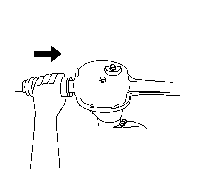
- Disconnect the left drive axle from the front differential.
- Make a reference mark on the pinion flange yoke and the differential pinion flange.
- Disconnect the propeller shaft from the front differential
- Support the front differential.
- Remove the front differential bolts.
- Lower the front differential and right drive shaft from the vehicle as an assembly.
- Using theJ 45531 remove the right drive axle from the front differential.
| • | The 4 skid plate bolts |
| • | The front skid plate |


Important: The drive axle circlip may break during the removal and possibly fall into the differential case. If this occurs, the pieces must be removed from the differential.
Important: The drive axle is retained with a circlip. If the circlip is off center, the drive axle is very difficult to remove. Center the circlip by rotating and lightly pulling on the drive axle. Continue rotating and pulling until the drive axle pops out about 1 mm (0.039 inch). This movement indicates that the circlip is now centered on the drive axle.
Installation Procedure
- Install the right drive axle shaft to the differential housing.
- Raise the front differential and right drive shaft as an assembly into position.
- Install the front differential retaining bolts.
- Align the reference marks, then connect the left drive axle to the differential.
- Align the front propeller shaft reference mark to the differential pinion flange.
- Install the propeller shaft retaining bolts
- Install the drive axle shaft spindle washer (1) onto the drive axle shaft.
- Install the drive axle shaft snap ring (2) onto the end of the drive axle.
- Apply General Motors Sealant, GM P/N 1052366 to the flange (1).
- Install the flange (1).
- Install the 6 flange bolts.
- Secure the flange bolts.
- Install the front tire and wheel assembly. Refer to Tire and Wheel Removal and Installation in Tires and Wheels.
- Lower the vehicle.

Notice: Use the correct fastener in the correct location. Replacement fasteners must be the correct part number for that application. Fasteners requiring replacement or fasteners requiring the use of thread locking compound or sealant are identified in the service procedure. Do not use paints, lubricants, or corrosion inhibitors on fasteners or fastener joint surfaces unless specified. These coatings affect fastener torque and joint clamping force and may damage the fastener. Use the correct tightening sequence and specifications when installing fasteners in order to avoid damage to parts and systems.
Tighten
Tighten the bolts to 50 N·m (37 lb ft).
Install the drive axle retaining bolts.
Tighten
Tighten the retaining bolts to 55 N·m (41 lb ft).
Tighten
Tighten the retaining bolts to 50 N·m (37 lb ft).


Tighten
Tighten the flange bolts to 48 N·m (35 lb ft).
