- Remove the power steering pump from the vehicle. Refer to
Power Steering Pump Replacement
.
- Clean the pump exterior thoroughly.
- Mount the pump in a table vise.
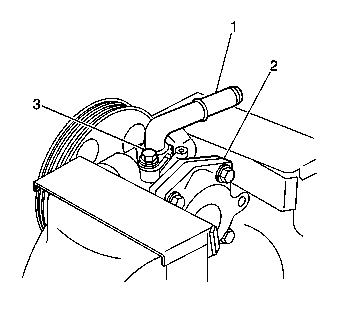
- Remove the following components from the pump body:
| • | The power steering gear outlet hose connector bolt |
| • | The power steering gear outlet hose connector (1) |
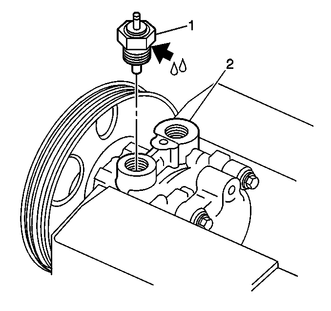
- Remove the pressure switch (1) from the pump body.
- Remove the flow control valve from the pump body.
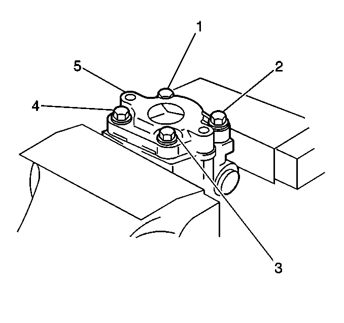
- Remove the 4 bolts (1,2,3,4) from the pump in order to
remove the rear pump cover and the O-ring seal from the pump body.
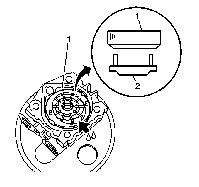
- Remove the cam ring (1) from the pump shaft.
Important: During disassembly, ensure that the vanes are kept together and identified
so that they can be reinstalled in the original locations.
- Remove the vanes from the rotor.
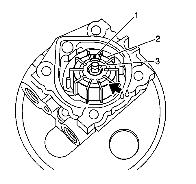
- Remove the following components from the pump body:
- Remove the shaft with the pulley attached from the pump body.
- Remove the oil seal from the pump body.
Inspection Procedure
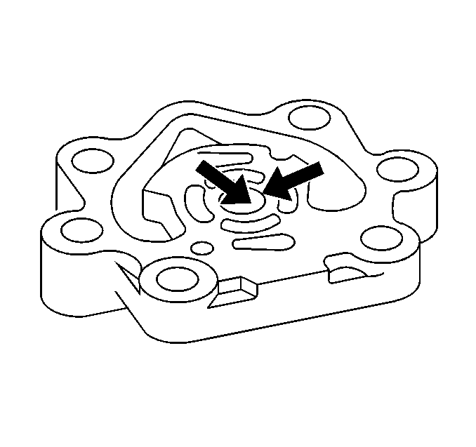
- Inspect the power steering
pump body and the cover for cracks or leaks.
- If any of the following conditions are present on the pump body
or any internal part, replace the power steering pump. Refer to
Power Steering Pump Replacement
.
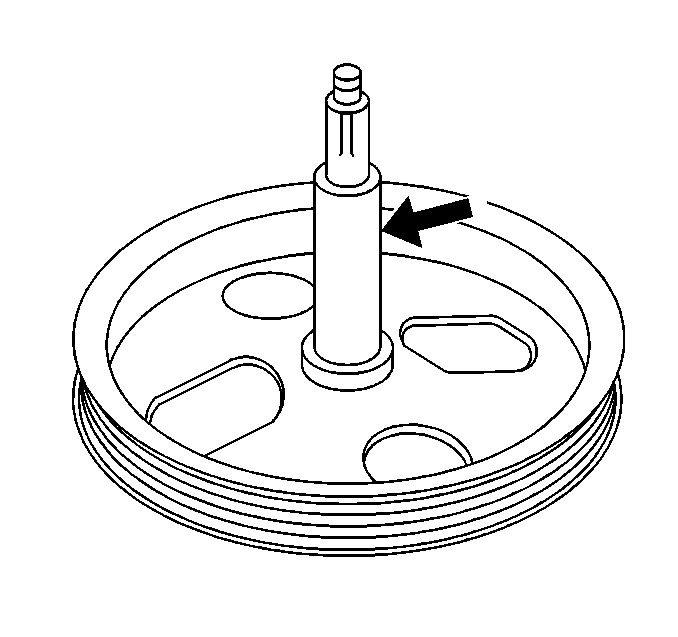
- Inspect the side plate
and the shaft for excessive wear and damage. If any defect is found, replace
the pump assembly. Refer to
Power Steering Pump Replacement
.
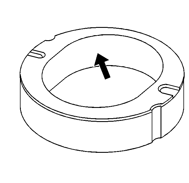
- Inspect the cam ring for excessive wear and damage. If any defect is
found, replace the pump assembly. Refer to
Power Steering Pump Replacement
.
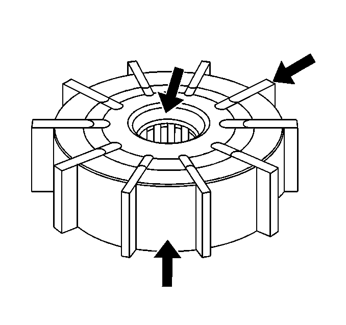
- Inspect the sliding surfaces of the rotor and the vane for wear and
damage. If wear or damage is present, replace the rotor and the vanes with
the power steering pump seal kit.
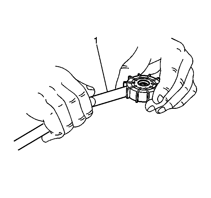
- Use a feeler gauge (1) in order to measure the vane-to-rotor
clearance.
Measurement
The allowable vane-to-rotor clearance is 0.015-0.027 mm
(0.0006-0.0011 in).
- If the vane to rotor clearance is greater than the specified range,
replace the rotor and the vanes with the power steering pump seal kit.
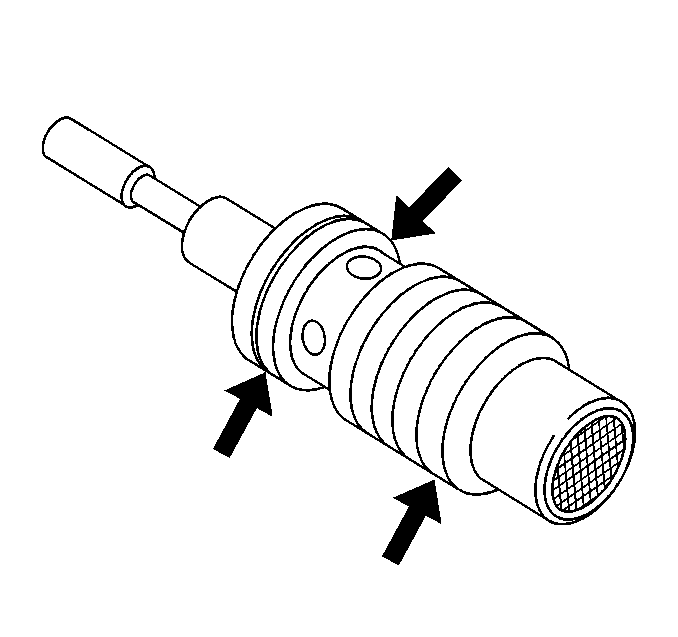
- Inspect the fluid passage of the relief valve and the orifice of the
connector for obstructions.
- Inspecting the sliding surface of the relief valve for wear and
damage.
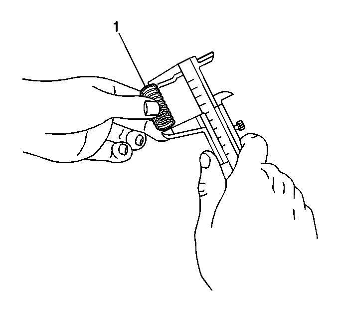
- Use the dial calipers in order to measure the free length of the flow
control valve spring (1).
Measurement
The free length of the spring should be within 19.0-22.0 mm
(0.748-0.866 in).
- If the valve spring does not fall within the specifications, replace
the power steering pump. Refer to
Power Steering Pump Replacement
.


