Power Steering Gear Inlet Pipe/Hose Replacement 1.6L
Removal Procedure
- Place a drain pan under the vehicle in order to catch any escaping fluid.
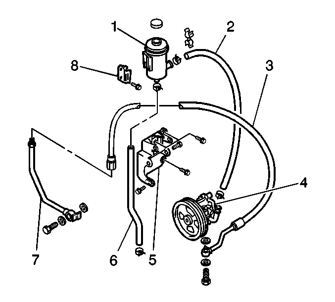
- Remove the power steering gear inlet hose fitting from the power steering pump (4).
- Remove the power steering gear inlet hose (3) and the 2 gaskets from the pump.
- Remove the power steering gear inlet hose from the power steering gear inlet pipe (7).
Notice: Refer to Power Steering Hose Disconnected Notice in the Preface section.

Important: The power steering gear inlet hose connects the power steering gear inlet pipe to the power steering pump.
Installation Procedure
- Install the power steering gear inlet hose (3) to the power steering gear inlet pipe (7).
- Install the power steering gear inlet hose and the 2 gaskets to the power steering pump (4).
- Install the hose fitting in order to retain the hose to the pump.
- Add power steering fluid to the reservoir. Refer to Checking and Adding Power Steering Fluid .
- Bleed the power steering system. Refer to Power Steering System Bleeding .
Notice: Refer to Fastener Notice in the Preface section.
Notice: Refer to Installing Hoses without Twists or Bends Notice in the Preface section.

Tighten
Tighten the power steering gear inlet hose to the power steering gear inlet pipe connection to 40 N·m (29 lb ft).
Tighten
Tighten the fitting to 60 N·m (43.5 lb ft).
Notice: Refer to Using Proper Power Steering Fluid Notice in the Preface section.
Notice: Refer to Air in the Power Steering System Notice in the Preface section.
Power Steering Gear Inlet Pipe/Hose Replacement 2.0L
Removal Procedure
- Place a drain pan under the vehicle in order to catch any escaping fluid.
- Remove the following components from the steering gear:
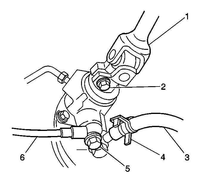
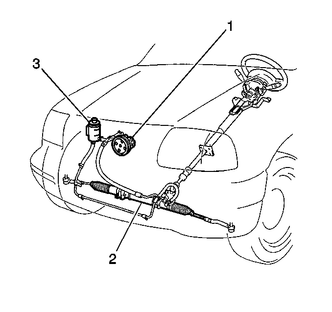
- Remove the power steering gear inlet hose fitting from the power steering pump (1).
- Remove the power steering gear inlet hose and the 2 gaskets from the power steering pump.
- Remove the power steering gear inlet hose from the bracket.
Notice: Refer to Power Steering Hose Disconnected Notice in the Preface section.

Important: The first design banjo bolt style fitting utilizes 2 gaskets. The second design flare nut style fitting utilizes seals.
| • | The power steering gear inlet hose fitting (5) |
| • | The 2 gaskets, if equipped |
| • | The power steering gear inlet hose (6) |

Installation Procedure
- Install the following components to the power steering pump (1):
- Install the following components to the steering gear:
- Install the power steering gear inlet hose to the hose bracket.
- Add fluid to the reservoir. Refer to Checking and Adding Power Steering Fluid .
- Bleed the power steering system. Refer to Power Steering System Bleeding .
Notice: Refer to Fastener Notice in the Preface section.
Notice: Refer to Installing Hoses without Twists or Bends Notice in the Preface section.

| • | The power steering gear inlet hose |
| • | The 2 gaskets |
| • | The fitting |
Tighten
Tighten the fitting to 60 N·m (43.5 lb ft).

Important: The first design banjo bolt style fitting uses 2 gaskets. The second design flare nut style fitting uses seals. The first design power steering components are not interchangeable with the second design power steering components.
| • | The steering gear inlet hose (6) |
| • | The 2 gaskets, if equipped |
| • | The fitting (5) |
Tighten
Tighten the fitting to 35 N·m (25.5 lb ft).
Notice: Refer to Using Proper Power Steering Fluid Notice in the Preface section.
Notice: Refer to Air in the Power Steering System Notice in the Preface section.
Power Steering Gear Inlet Pipe/Hose Replacement 2.5L
Removal Procedure
- Place a drain pan under the vehicle in order to catch any escaping fluid.
- Remove the following components from the steering gear:
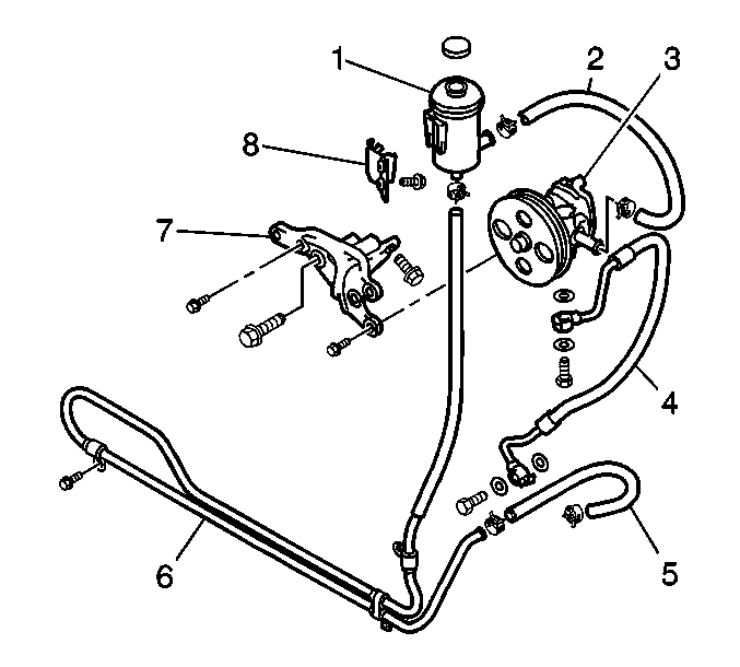
- Remove the power steering gear inlet hose fitting from the power steering pump (3).
- Remove the power steering gear inlet hose (4) and the 2 gaskets from the pump.
Notice: Refer to Power Steering Hose Disconnected Notice in the Preface section.

Important: The first design banjo bolt style fitting utilizes 2 gaskets. The second design flare nut style fitting utilizes seals.
| • | The power steering gear inlet hose fitting (5) |
| • | The 2 gaskets, if equipped |
| • | The power steering gear inlet hose (6) |

Installation Procedure
- Install the following components to the power steering pump (3):
- Install the following components to the steering gear:
- Add fluid to the reservoir (6). Refer to Checking and Adding Power Steering Fluid .
- Bleed the power steering system. Refer to Power Steering System Bleeding .
Notice: Refer to Fastener Notice in the Preface section.
Notice: Refer to Installing Hoses without Twists or Bends Notice in the Preface section.

| • | The power steering gear inlet hose (4) |
| • | The 2 gaskets |
| • | The fitting |
Tighten
Tighten the fitting to 60 N·m (43.5 lb ft).

Important: The first design banjo bolt style fitting uses 2 gaskets. The second design flare nut style fitting uses seals. The first design power steering components are not interchangeable with the second design power steering components.
| • | The steering gear inlet hose (6) |
| • | The 2 gaskets, if equipped |
| • | The fitting (5) |
Tighten
Tighten the fitting to 35 N·m (25.5 lb ft).
Notice: Refer to Using Proper Power Steering Fluid Notice in the Preface section.
Notice: Refer to Air in the Power Steering System Notice in the Preface section.
