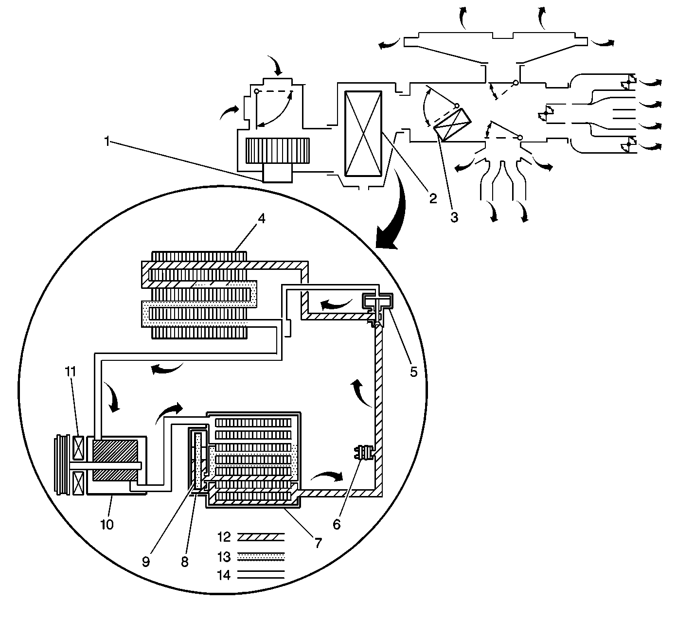
The air temperature controls are divided into three primary areas. The first, Heater Mode, is related to how the heater system responds when a heater mode is selected, and how the HVAC system provides the desired temperature for each setting. The second, A/C Mode, is related to how the A/C system responds when an A/C mode is selected by the vehicle operator, and how the HVAC system provides the desired temperature for each setting. The third, A/C Cycle, describes the complete A/C cycle.
Heater Mode
The purpose of the heater is to supply heat to the interior of the vehicle. The vehicle operator can determine the level of heat by turning the temperature control, located on the HVAC control unit, to any setting. The temperature control can change the vehicle's air temperature regardless of the HVAC mode setting; heater or A/C.
The air temperature is controlled by moving the temperature control lever. Moving the air temperature lever mechanically moves the air temperature door. They are linked together by the air temperature cable. The air temperature door position determines the amount of air directed to flow across the heater core.
Engine Coolant
Engine coolant is the key element of the heating system. The normal engine operating coolant temperature is controlled by the thermostat. The thermostat also creates a restriction for the cooling system that promotes a positive coolant flow and helps prevent cavitation.
Coolant enters the heater core through the inlet heater hose, in a pressurized state. The heater core is located inside the HVAC module. The heat of the coolant flowing through the heater core is absorbed by the ambient air drawn through the HVAC case. Heated air is distributed to the passenger compartment, through the HVAC case, for passenger comfort. The amount of heat delivered to the passenger compartment is controlled by opening or closing the HVAC case temperature door. The coolant exits the heater core through the return heater hose and recirculated back through the engine cooling system.
A/C Mode
The purpose of the air conditioning (A/C) system is to provide cool air and remove humidity from the interior of the vehicle. The vehicle operator can activate the A/C system by depressing the A/C switch or by placing the mode control in Defrost position. The blower switch must be in any position except OFF for the A/C system to operate. The A/C system can operate regardless of the temperature setting.
Regardless of the selected A/C mode setting, a request is made to the A/C compressor control module to turn on the A/C compressor. The request is sent to the A/C compressor control module through the A/C request signal circuit from the defrost switch or from the A/C switch. The A/C compressor control module and the A/C switch each receive ignition voltage through the IG fuse in the junction block. The defrost switch is in parallel with the A/C switch. The A/C compressor control module is grounded at G103. The A/C request circuit is grounded through the blower switch at G201 when the blower switch is in any position except OFF and either the A/C switch or the defrost switch is closed.
When the A/C switch is depressed, and the blower switch is in any position except OFF, a light emitting diode (LED) within the A/C switch illuminates by grounding through the blower switch at G201. When the A/C compressor control module receives an A/C request, the A/C compressor control module provides a signal to the powertrain control module (PCM) for idle control.
In order for the A/C compressor control module to internally ground the A/C clutch relay control circuit, the A/C refrigerant pressure switch must be closed and the evaporator temperature sensor must correspond to an evaporator core temperature of 0°-25°C (32°-77°F). With both these reference signals, the A/C compressor control module can activate the A/C compressor clutch.
The A/C compressor control module turns on the A/C compressor by providing a path to ground through the A/C clutch relay control circuit for the A/C compressor clutch relay. Ignition voltage is provided to the A/C compressor clutch relay coil from the DEF fuse in the junction block. Battery voltage is provided to the A/C compressor clutch relay switch through the HTR fuse in the fuse block. Once the relay closes its internal switch, power from the battery is provided to the A/C compressor clutch through the A/C compressor clutch supply voltage circuit. Whenever the compressor is turned on, the A/C compressor clutch diode prevents a voltage spike from burning up the compressor clutch coil. The engine block provides a pathway to ground for the compressor. The A/C clutch relay control circuit is grounded internally within the A/C compressor control module.
A/C Pressure Switches

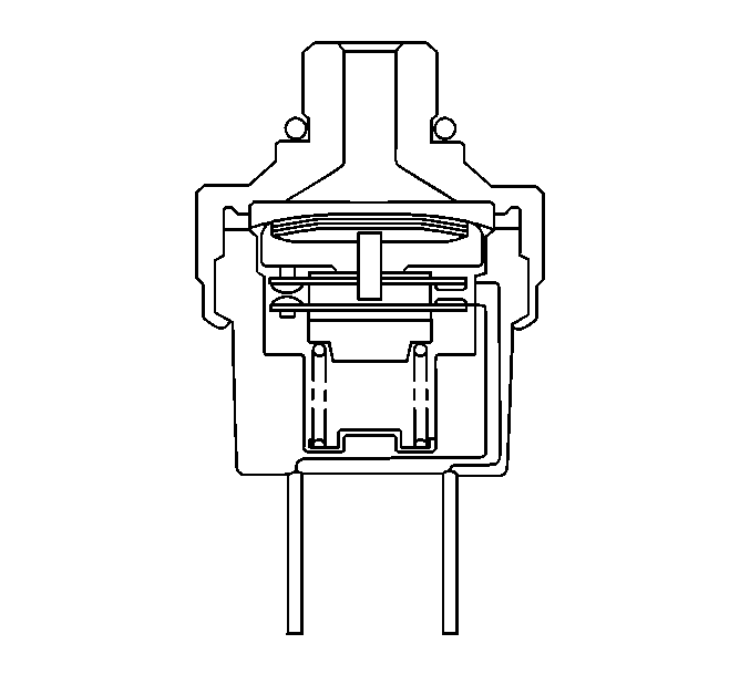
The A/C system is protected by two pressure switches. The A/C high pressure switch opens when the A/C line pressure exceeds a predetermined value (3140 kPa (455 psi)). The A/C low pressure switch opens when the A/C line pressure falls below a predetermined value (196 kPa (28 psi)). When the A/C compressor control module sees an open in either signal, the A/C clutch relay control circuit is no longer grounded, thus shutting off the compressor. The A/C refrigerant pressure sensor is located next to the condenser fan motor in the liquid line, between the receiver/ dryer and the evaporator. The A/C refrigerant pressure sensor incorporates both the high and the low pressure switches in one unit.
The A/C compressor control module monitors the evaporator temperature sensor which is mounted on the inside of the evaporator housing. The evaporator temperature sensor converts evaporator core temperature into a resistance value. Using this resistance value, the A/C compressor control module can sense when the evaporator temperature drops below 0°C (32°F). If this occurs, the A/C compressor control module removes the A/C compressor clutch relay coil ground. This prevents evaporator frost and ice build-up which reduces airflow and reduces the cooling capacity of the unit.
Temperature Control
The vehicle operator can determine the temperature of the A/C air by using the temperature control. The temperature control cable opens the air mixture door to a position to divert sufficient air past the evaporator to achieve the desired vehicle temperature. Warm heater air is mixed with cool A/C air at the air mixture door. When the coldest temperature setting is selected, no warm heater air is mixed with the cool A/C air.
Condenser Fan Control
The condenser fan ensures a sufficient amount of airflow across the condenser throughout the vehicle's operating range. Ignition voltage is applied to the coil side of the condenser fan relay through the DEF fuse. Battery voltage is applied to the switch side of the condenser fan relay through the HTR fuse. When the relay is energized, battery voltage is applied to the A/C condenser fan through the A/C fuse and the closed contacts of the relay. Since the A/C condenser fan is grounded at G105, the condenser fan operates as long as the relay is energized. The PCM will ground the condenser fan relay coil under any of the following conditions:
| • | The A/C system is operating. |
| • | The ECT is 113°C (235°F) or higher indicating an overheating condition. |
| • | The PCM detects an ECT sensor malfunction. |
The PCM monitors engine coolant temperature (ECT). If the ECT rises above 113°C (235°F), indicating an overheating condition, the PCM sends a cut out signal to the A/C compressor control module, prompting the A/C compressor control module to disengage the A/C compressor clutch in order to reduce engine load. The PCM sends a cut out signal to the A/C compressor control module under any one of the following conditions:
| • | The ECT is 113°C (235°F) or higher. |
| • | After opening the throttle valve 71 degrees or more. |
| • | When the engine speed is less than 500 RPM, or greater than 6500 RPM. |
| • | The A/C compressor control module signal is absent. |
A/C Cycle

