Visual Aiming Procedure
| • |
All equipment for testing headlamps must
comply with the SAE Recommended Practice for Headlamp Inspection Equipment. |
| • | If you use a headlamp testing machine, the machine should give results
equivalent to the results obtained using the screen procedure. |
| • | The machine should be in good condition and be properly adjusted. Use the machine in accordance with the manufacturer's instructions.
|
| • | Machines that use a photoelectric cell or cells to determine aim, should
also include a visual screen on which you can project a beam pattern proportional
to the beam appearance, and aim on a screen at 10 m (32.8 ft). |
| - | The screen should be plainly visible to the technician who is adjusting
the headlamps. |
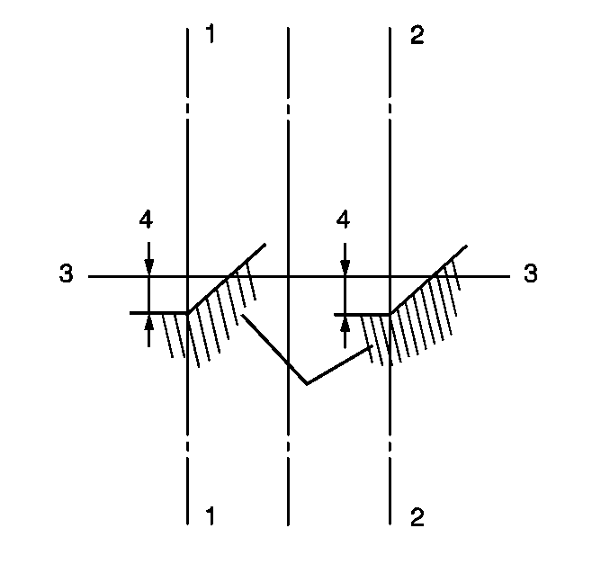
| - | The screen should have horizontal (3) and vertical (1,2)
reference lines in order to permit visual evaluation of the headlamp beam. |
Headlamp Aiming Location (Using Screen Method)
| • |
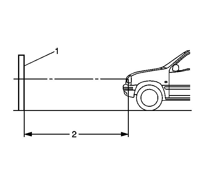
The aiming area should be darkened and
large enough to allow for the vehicle and an additional 10 m (32.8 ft),
measured from the face of the headlamps (2) to the front of the screen (1). |
| • | The floor on which the vehicle rests must be parallel with the bottom
of the screen. If the floor is not level, compensate accordingly.
|
Headlamp Aiming Screen
| • |

If you use a screen, the screen should
be at least 1.52 m (5 ft) high x 3.66 m (12 ft) wide
with a matte white finish, well shaded from extraneous light. |
| • | Properly adjust the screen to the floor on which the vehicle rests. |
| • | The screen should be moveable so that you can align the screen parallel
to the rear axle of the vehicle. |
| • | Position the screen so that a horizontal line (3) drawn perpendicular
to the centerline of the screen will pass an equal distance midway between the
two headlamps. |
| • | The screen should have the following items: |
| - | Two laterally adjustable vertical tapes (1,2) |
| - | One vertically adjustable horizontal tape |
| • | If a regular commercial aiming screen is not available, the screen may
consist of a wall having a clear, uninterrupted area at least 1.83 m (6 ft)
x 3.66 m (12 ft) wide. The surface should be finished with a no-gloss
white paint. |
| • | After the aiming screen has been set up and located, paint or tape a
reference line on the floor 7.62 m (25 ft) from the screen. Park
the vehicle with the front of the headlamps directly over this reference line. |
Headlamp Aiming Procedure
- Park the vehicle square with the screen, with the headlamps directly
over this reference line.
- Ensure that the components are in place if other work has been done on
the vehicle.
- Ensure that the vehicle is on a level surface.
- Stop all other work on the vehicle.
- Ensure that the vehicle has half a tank, or less, of fuel.
- Close all of the doors.
- Rock the vehicle sideways.
- Line up the centerline of the vehicle with the centerline of the aiming
screen.
| • | Mark the vertical center of the rear and front windows using tape. |
| • | Use these lines as sights in order to line up the centerline of the vehicle
and the screen. |
- Adjust the vertical tapes on the screen in order to match the vertical
centerline of each low beam headlamp.
Measure the distance from the centerline of the low beam lamp.
- Adjust the horizontal tapes on the screen in order to match the horizontal
centerline of each low beam headlamp.
Measure the height from the floor to the center of the low beam.
- Turn on the low beam headlamps.
- Observe the left and the top edges of the high intensity zone on the
screen.
- Adjust the headlamps to the following specifications:
| • | The top edge of the center of intensity on the screen for the low beam
should be less than 101.6 mm (4 in) above or below the cross section
of the headlamp centerlines. |
| • | The left edge of the center of intensity on the screen for the low beam
should be less than 101.6 mm (4 in) to the left or right of the
cross section of the headlamp centerlines. |
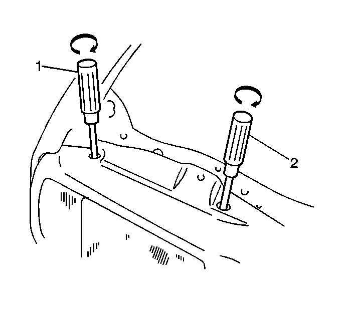
- In order to adjust the horizontal aim,
insert the screwdriver (2) and turn the horizontal headlamp adjusting screw.
- In order to adjust the vertical aim, insert the screwdriver (1)
and turn the vertical headlamp adjusting screw.
Alternative Headlamp Aiming Procedure
Tools Required
J 25300-D Headlamp Aiming
Kit
Properly aim the headlamps in order to obtain the maximum road illumination
and safety of the headlamp system. Always aim the headlamps if removing the headlamp
assembly from the vehicle. Composite headlamps do not require aiming if replacing
only the bulb.
When inspecting or adjusting the headlamp aim, observe the following conditions:
| • | Ensure the vehicle is on a level surface. |
| • | Inflate all of the tires to the specified pressure. Refer to the tire placard for tire pressure specifications. Refer to
Tire Placard
in General Information for the location
of the tire placard.
|
| • | Inspect vehicles that tow a trailer or carry an unusual load under the
same conditions. |
| • | Clean the headlamps before aiming. |
| • | Follow the state requirements for headlamp aiming. |
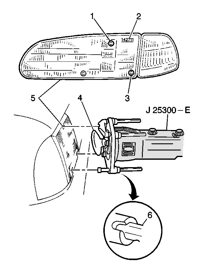
The J 25300-D
is designed
to accommodate all composite and sealed beam headlamps in any standard shape
or size and in any configuration. Use the adapters provided in kits for
different lamp shapes and sizes. Regardless of the configuration, aim the headlamps
in pairs.
Use the following list in addition to the mounting and adjustment instructions
included in the J 25300-D
in order to aim the headlamps
- Use the universal aimer on a level floor, or calibrate the aimer for the floor
slope.
- Select and assemble the universal adapter which matches the aiming pad
pattern on the lens of the headlamp.
- Align the selected adapter to the aiming pads.
Move the adjustment rod for each pad until correlated with the adjustment rod
setting numbers located on the headlamp.
On some headlamps, the numbers are located on the lower edge of the vertical
edge of the lens.
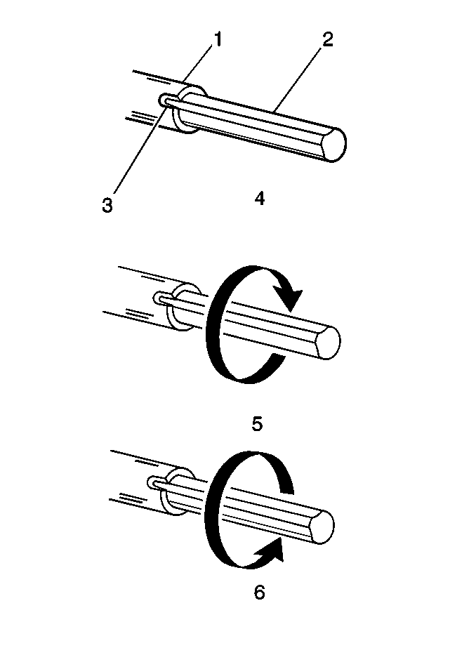
- In order to adjust the rods (2) to the required positions, turn
the rods (2) to the neutral position (4).
Slide the rods in or out to the proper setting.
- Verify that the correct adapter is issued
using the correct side aimer.
- Attach the adapters. Using the adapters, place the aimer onto the respective
sides.
- Ensure the all adjustment rods (6) and the articulating suction
cups (4) are contacting the aiming pads (1,3).
- Add or remove extension studs as needed.
- Aim the headlamps according to the instructions included with the J 25300-D
.

- In order to adjust the horizontal aim,
insert the screwdriver (2) and turn the horizontal headlamp adjusting screw.
- In order to adjust the vertical aim, insert the screwdriver (1)
and turn the vertical headlamp adjusting screw.


