GM Service Manual Online
For 1990-2009 cars only
Makes
🢒
Chevrolet
🢒
2001
🢒
Tracker - 4WD
🢒
Body and Accessories
🢒
Wiring Systems
🢒 Antilock Brake System Schematics
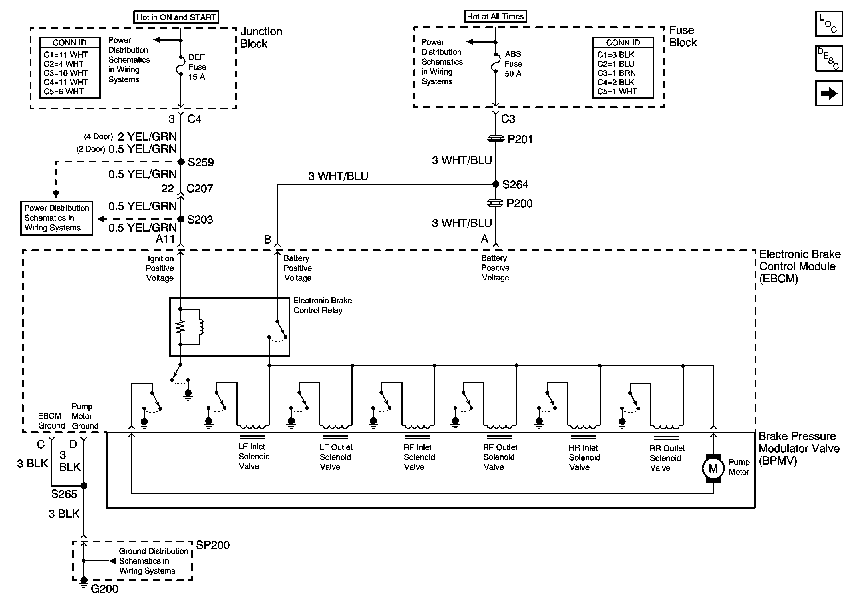
Figure
1:
Brake Pressure Modulator Valve
Master Electrical Component List
ABS Description and Operation
ABS Indicator, Accelerometer, and Idle Up Signal
BATT, ABS, FI and ACC Fuses
G200 (1 of 2)
CIG, DEF and P/W Fuses
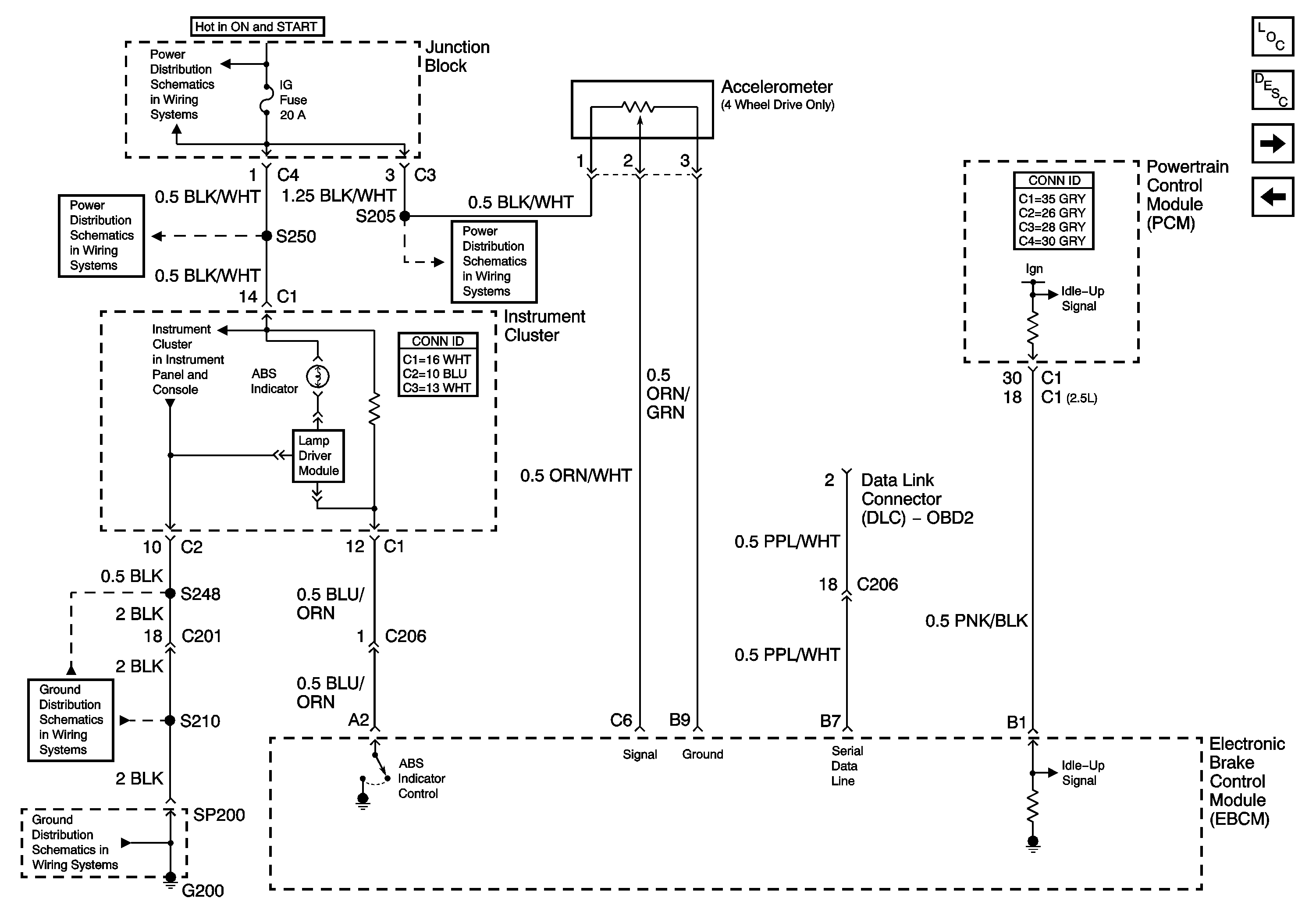
Figure
2:
ABS Indicator, Accelerometer, and Idle Up Signal
Master Electrical Component List
ABS Description and Operation
Brake Fluid Level Indicator, Brake Indicator and Stoplamp Switch
Brake Pressure Modulator Valve
IG Fuse
IG Fuse
IG, Turn and WIP Fuses
ABS Indicator, Brake Indicator, Air Bag Indicator
G200 (1 of 2)
G200 (1 of 2)
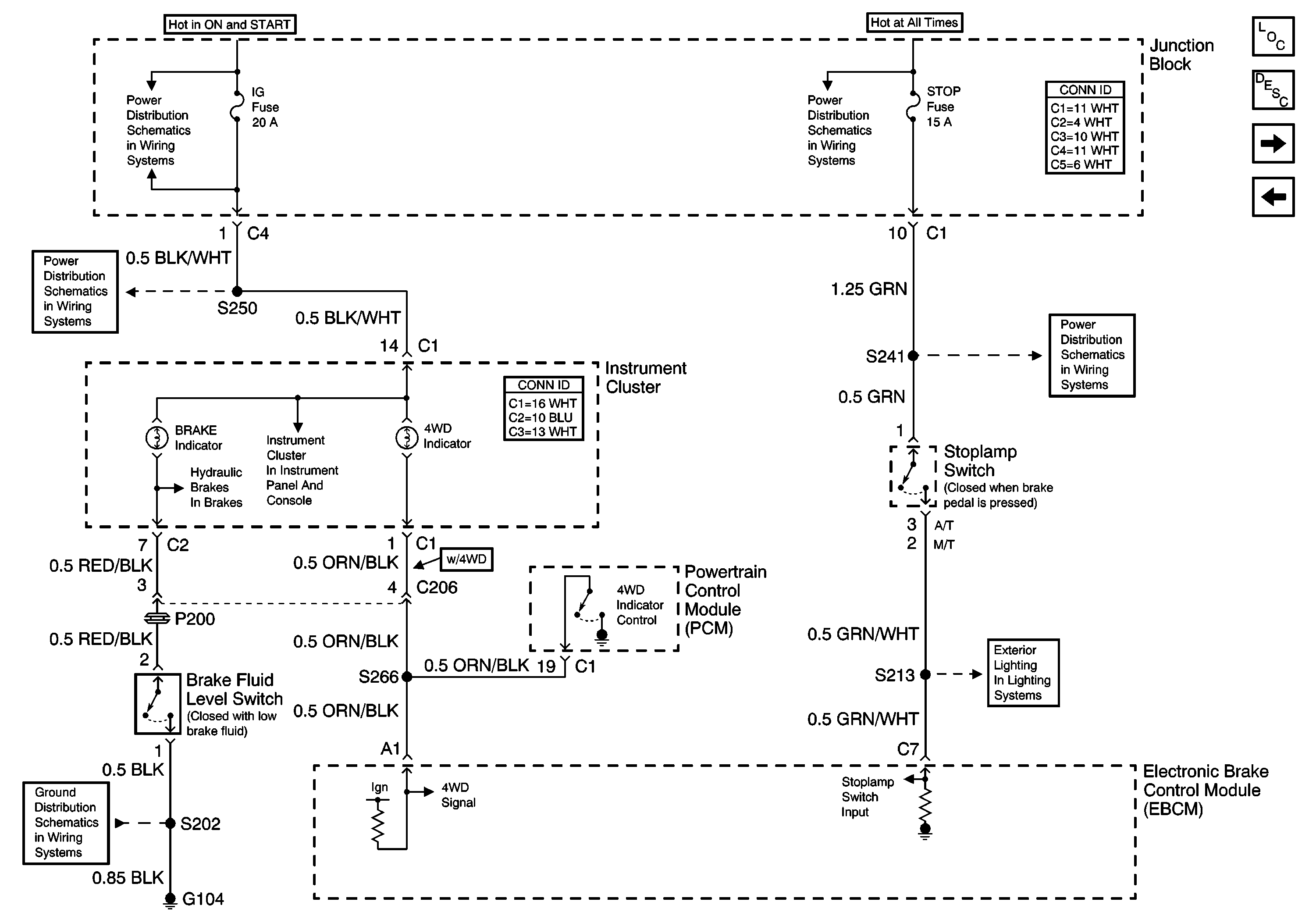
Figure
3:
Brake Fluid Level Indicator, Brake Indicator and Stoplamp Switch
Master Electrical Component List
ABS Description and Operation
Wheel Speed Sensors
ABS Indicator, Accelerometer, and Idle Up Signal
HAZ, D/L, TAIL, Stop and Dome Fuses
Center High Mount Stoplamp (CHMSL)
HAZ, D/L, TAIL, Stop and Dome Fuses
IG Fuse
NO TITLE BRAKES
Instrument Cluster Indicators
G104
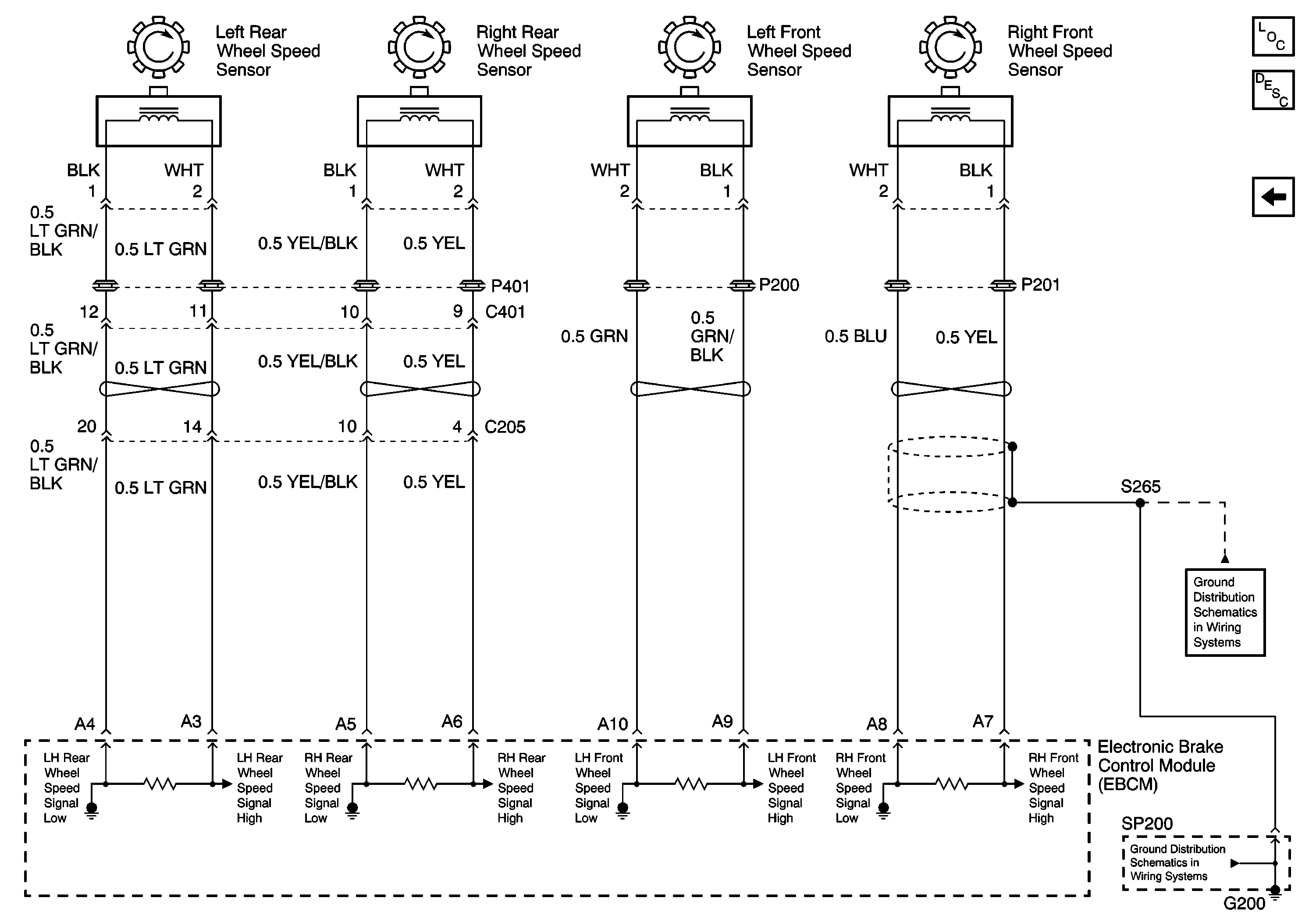
Figure
4:
Wheel Speed Sensors
Master Electrical Component List
ABS Description and Operation
Brake Fluid Level Indicator, Brake Indicator and Stoplamp Switch