Removal Procedure

- Remove the fluid level
indicator.
- Raise the vehicle. Support the vehicle. Refer to
Lifting and Jacking the Vehicle
in General Information.
- Remove the front propeller shaft. Refer to
Front Propeller Shaft Replacement
.
- Remove the 4 nuts and the 4 bolts from the front
differential pinion flange (four-wheel drive models).
- Separate the pinion flange yoke from the front differential pinion
flange (four-wheel drive models).
- Position and support the transfer case to the front differential
propeller shaft away from the transmission fluid pan.
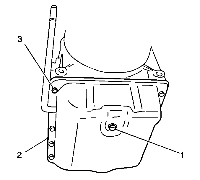
- Place a drain pan or suitable container under the transmission
drain plug (1).
- Remove the drain plug in order to allow the transmission fluid
pan (2) to drain.
- Remove the 14 transmission fluid pan bolts (3) from
the transmission fluid pan.

- Remove the transmission fluid pan and the gasket from the transmission.
- Remove the solenoid harness.
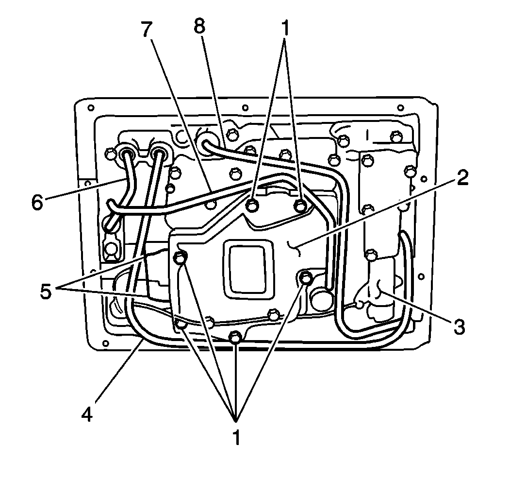
- Remove the following items from the valve body:
| • | The fluid filter screen (2) |
| • | The fluid filter gasket |
| • | The fluid filter spacer |
| • | The fluid filter spacer gasket |
Important: A small amount of clutch material in the bottom of the transmission
fluid pan is a normal condition and is consistent with normal transmission
wear. The bottom of the fluid pan is equipped with a magnet
that will collect minute metal filings. However, if large amounts
of clutch material, metal shavings or other foreign matter are
present, transmission disassembly and inspection is indicated.
- Clean the fluid filter screen with solvent and air dry.
- Clean the transmission fluid pan with solvent and air dry.
- Clean the fluid pan magnets with solvent and air dry.
- Clean the transmission fluid pan.
- Clean the fluid filter screen gasket mating surfaces
- Inspect the fluid filter screen for tears or other damage.
- Replace as necessary.
Installation Procedure

- Install a new fluid filter screen gasket and fluid filter screen (2)
to the valve body.
Notice: Use the correct fastener in the correct location. Replacement fasteners
must be the correct part number for that application. Fasteners requiring
replacement or fasteners requiring the use of thread locking compound or sealant
are identified in the service procedure. Do not use paints, lubricants, or
corrosion inhibitors on fasteners or fastener joint surfaces unless specified.
These coatings affect fastener torque and joint clamping force and may damage
the fastener. Use the correct tightening sequence and specifications when
installing fasteners in order to avoid damage to parts and systems.
- Secure the fluid
filter screen (2) to the valve body with the 6 bolts (1).
Tighten
Tighten the fluid filter screen bolts to 5 N·m (44 lb in).
- Install the solenoid harness.
Important: Ensure the filler tube is properly connected when installing the transmission
pan.
- Install the new transmission fluid pan gasket and the transmission fluid
pan to the transmission.
- Secure the transmission fluid pan with the fourteen bolts.
Tighten
Tighten the transmission fluid pan bolts to 5 N·m (44 lb in).

- Install the transmission
drain plug (1) into the transmission.
Tighten
Tighten the transmission drain plug to 17 N·m (13 lb ft).
- Install the propeller shaft into the vehicle. Refer to
Front Propeller Shaft Replacement
.
- Lower the vehicle.

- Refill the transmission
as necessary using the following steps:
| 9.1. | Place the vehicle on a level surface. |
| 9.2. | Add approximately 2.5 liters (2.6 quarts) of Dexron®-III
automatic transmission fluid GM P/N 12346143 (Canadian P/N 10952622),
or the equivalent, into the fluid filler tube. |
| 9.3. | Install the fluid level indicator into the fluid filler tube. |
| 9.4. | Apply the parking brake and block the vehicle wheels. |
| | Important: DO NOT race the engine.
|
| 9.5. | With the selector lever in the PARK position, start the engine. |
| 9.6. | Run the engine at idle speed. |
| 9.7. | Move the selector lever through each range and return the selector
lever to the PARK position. |
| 9.8. | While the engine is running at idle remove the fluid level indicator
from the filler tube and wipe the indicator off. |
| 9.9. | Reinsert the fluid level indicator into the filler tube making
sure it is seated in its original position. |
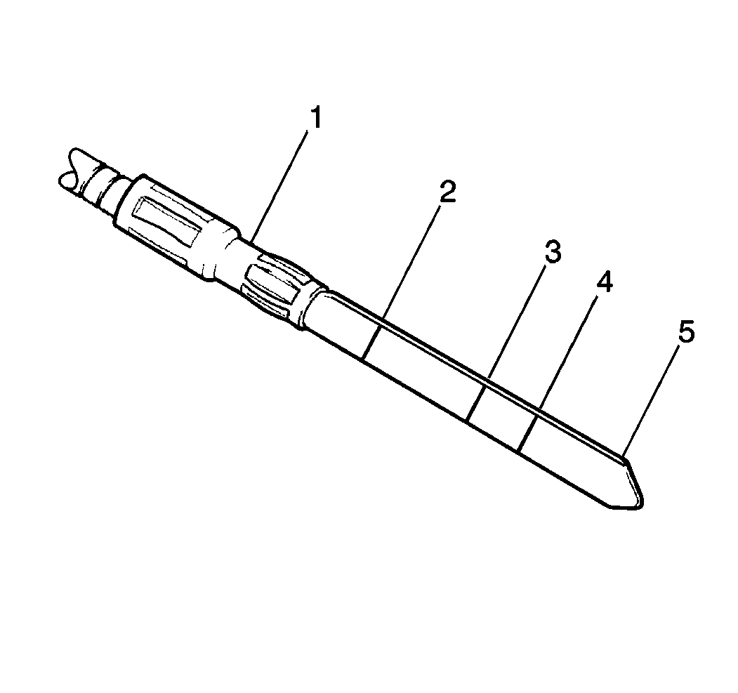
| 9.10. | Remove the indicator and check the fluid level. The level should
be between the FULL HOT (2) and the LOW HOT (3) marks. If the level is below
the LOW HOT mark, add fluid to bring the level to the FULL HOT
mark. Bringing the fluid level from the LOW HOT mark to the FULL
HOT mark requires 0.3 liters (0.3 quarts) of fluid.
Use Dexron®-III automatic transmission fluid GM P/N 12346143
(Canadian P/N 10952622), or the equivalent. |
| 9.11. | Conduct a road test and check the transmission level. |


