This procedure is designed to fine-tune the balance of the propshaft while it is mounted in the vehicle. The propeller shaft and the pinion flange runouts should be within tolerances before attempting to balance the system.
Strobe Balance Testing with the Electronic Vibration Analyzer (EVA)
Ensure that the runout of the various driveline components are within specifications. If the runouts are within specifications, strobe balance the driveline. The EVA is able to simplify the balancing process, using the following procedure:
- Turn the ignition ON.
- Place the transmission in NEUTRAL.
- Remove the rear tire/wheel assemblies. Refer to Tire and Wheel Removal and Installation in Tires and Wheels.
- Remove the brake drums. Refer to Brake Drum Replacement in Drum Brakes.

If the shaft will not balance using two weights, place a third weight on the light spot. Split the first two weights in order to produce a total weight between two and three weights.
If three weights fail to balance the driveline, replace the propeller shaft.
When the propeller shaft balances, road test the vehicle in order to verify that the vibration is eliminated.
Driveline System Balance without the Electronic Vibration Analyzer (EVA)
The following procedure is designed to fine-tune the balance of the propeller shaft while it is mounted in the vehicle. This procedure will also correct residual imbalance of the remaining driveline components.
Prior to balancing the driveline system, verify that the propeller shaft and the pinion flange runout are within specification.
Do not overheat the engine when performing this procedure.
- Raise the vehicle to curb height. Support the vehicle on a hoist or on safety stands. Do not allow the axle to hang. Refer to Lifting and Jacking the Vehicle in General Information.
- Remove the rear tire/wheel assemblies. Refer to Tire and Wheel Removal and Installation in Tires and Wheels.
- Remove the brake drums. Refer to Brake Drum Replacement in Drum Brakes.
- Determine which end of the propeller shaft has the most vibration in order to identify where to begin installing the hose clamps.
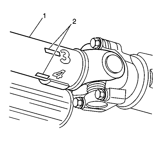
- Mark the end of the propeller shaft (1) which has the most vibration at 4 points (2), 90 degrees apart. Number the marks 1-4.

| (1) | Propeller Shaft |
| (2) | Chalk Marks |
The following procedure uses a trial and error method of determining where to place the hose clamps on the shaft. Use the following tips in order to help locate the clamps:
- Because the imbalance may be related to propeller shaft runout, begin installing the clamps at the low point of the propeller shaft runout.
- When the plant workers balance the propeller shaft, they use weights in graduated increments: 1/16 oz, 1/8 oz, etc. If the stock weight is too light or too heavy, place the hose clamp either directly in line with or opposite to the stock weight.
The last method involves running the vehicle at a speed which the vibration is felt.
- Carefully hold a piece of chalk up to the very end of the propeller shaft. Barely touch the chalk to the shaft.
- Shut the engine OFF in order to stop the propeller shaft from rotating. Do not step on the brake pedal. Do not put the transmission in PARK.
- Inspect the chalk mark.
If you performed the above procedure correctly, the chalk mark will indicate the heavy spot on the shaft. The heavy spot will deflect downward and touch the chalk. If the chalk mark circles the entire shaft, touch the chalk more gently to the shaft. Ensure that the chalk touches only the heavy spot. Once the heavy spot is located, place the hose clamp 180 degrees opposite to the chalk mark. Perform the following steps:
- Place the hose clamp at the light spot, or at any of the 4 points marked previously.
- Test drive the vehicle at the speed at which the vibration occurred. Record any changes in the vibration.
- Move the clamp to the other positions.
- Test drive the vehicle each time you move the clamp. Record any changes in vibration. Remember which position gives the best balance.

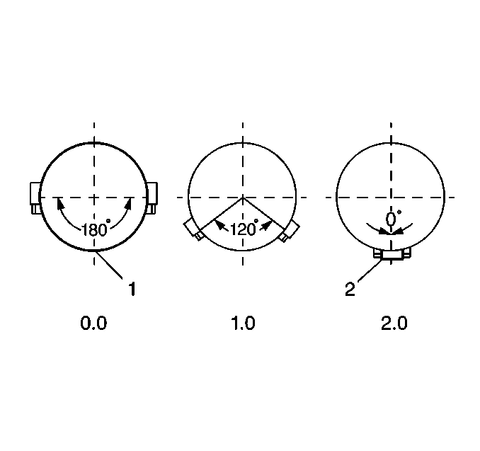
| (1) | Balance Location |
| (2) | Clamps Together |
| • | If the vibration did not change at all or if the vibration becomes worse, then 1 clamp is either too light or too heavy. Repeat the procedure using the 2 clamps together. |
| • | If the previous step did not correct the problem, repeat the procedure using the 2 clamps separated in order to reduce the spinning weight. |
Continue the trial and error procedure using different weights in different locations until you achieve the best balance. If more that 3 clamps aligned in the same position are required, replace the propeller shaft.
If you are able to reduce the vibration in the stall, but are unable to eliminate the vibration completely, perform a road test on the vehicle. A slight vibration noticeable in the stall may not be noticeable on the road.
Propeller Shaft Balance Weights
When using clamps in order to balance a propeller shaft with the total weight method, the correction weight required will often be a fraction or a multiple of one hose clamp. Use the following phasing procedure with two hose clamps in order to accurately place any required amount 0-2 weights (0.0-2.0 total weights).
- Ensure that the clamps are located with even spaces on either side of the light spot, or 180 degrees opposite the heavy spot.
- If the vibration does not change at all or gets worse, then one clamp is too light or too heavy. Repeat the procedure using the two clamps together.
- If the previous step did not correct the problem, repeat the procedure using the 2 clamps separated in order to reduce the spinning weight.
- Continue the trial and error procedure using different weights in different locations until you achieve the best balance.
- If more than three clamps aligned in the same position are required, replace the propeller shaft.
- If you are able to reduce the vibration in the stall, but are unable to eliminate the vibration completely, road test the vehicle. A slight vibration noticeable in the stall may not be noticeable on the road.

| (1) | Balance Location |
| (2) | Clamps Together |
The table containing the weight amounts in terms of the total weight and the included angle (spread) between the clamps is in specifications.
