Tools Required
| • | J 23498-20 Driveshaft Inclinometer Adapter |
| • | J 23498-A Driveshaft Inclinometer |
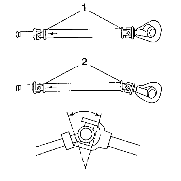
Driveline working angle does not refer to the angle of any one shaft, but to the angle that is formed by the intersection of two shafts.
The procedure for measuring and correcting driveline working angles depends on whether the vehicle is equipped with a propeller shaft consisting of one piece or two pieces.
In order to verify the accuracy of theJ 23498-20 , inspect the angle of an accessible joint with the inclinometer prior to assigning the adapter on an inaccessible joint.
One- Piece Propeller Shaft System
- Raise the vehicle on a suitable hoist or on safety stands. Ensure that the rear axle is supported at curb height and that the wheels are free to spin. Refer to Lifting and Jacking the Vehicle in General Information.
- Place the transmission in NEUTRAL.
- Ensure that the vehicle has a full tank of fuel or the equivalent amount of weight in the rear to simulate a full tank. The weight of 3.8 liters of gasoline (1 gallon) is approximately 2.8 kg (6.2 lb).
Measuring One - Piece Propeller Shaft Working Angles
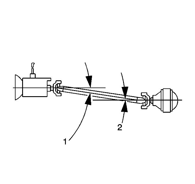
The working angle of a U-joint is the difference between the angles formed when two shafts intersect. One piece propeller shaft systems have two working angles, the front (1) and the rear (2).
| • | The two working angles should be equal within 1/2 of a degree. |
| • | The working angles should not exceed 4 degrees. |
| • | The working angles should not be equal to zero because a 0 degree working angle will cause premature U-joint wear due to lack of rotation of the U-joint. |
| • | The angle formed by the propeller shaft and the rear axle pinion form the rear working angle (2) |
| • | The angle formed by the propeller shaft and the transmission output shaft form the front working angle (1) |
The angles of these components are most accurately measured from the U-joint bearing caps. Verify that the bearing caps are free of corrosion or foreign material in order to ensure accurate readings. Remove any snap rings that may interfere with the correct placement of the inclinometer. Reinstall the snap rings after you take the measurements.
Take the measurements from the same side of the propeller shaft in order to maintain consistent angle measurements (either on the driver side or on the passenger side).
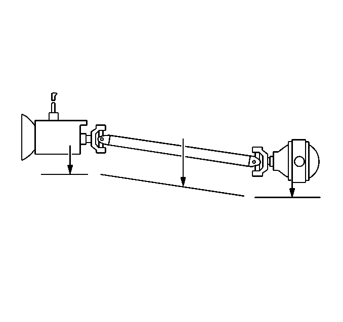
Record the readings on a diagram like the one shown as you proceed through the measurements.
Evaluation
The two working angles in a one-piece propeller shaft system should be equal to within 1/2 of a degree for effective cancellation.
Two-Piece Propeller Shaft System
Two-piece propeller shaft systems have three working angles instead of two working angles as in the one-piece systems.
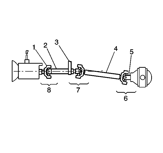
| • | The first angle is the front working angle (8). It is formed by the angle of the output shaft of the transmission and the angle of the front propeller shaft. |
| • | The second angle (7) is the middle working angle. It is formed by the angle of the front propeller shaft and the angle of the rear propeller shaft. |
| • | The third angle (6) is the rear working angle. It is formed by the angle of the rear propeller shaft and the angle of the pinion yoke of the rear axle. |
If the launch shudder or the second-order driveline vibration is still present, measure and correct the driveline angles.
Two-Piece Propeller Shaft Lateral Alignment
The procedure for lateral alignment of a two-piece propeller shaft is used for launch shudder or any second-order driveline vibrations. Adjust the lateral alignment before you measure and adjust the driveline angles.
- Raise and suitably support the vehicle on a hoist. Refer to Lifting and Jacking the Vehicle in General Information.
- Look down the front of the propeller shaft.
- If the propeller shaft is not straight, or if the center bearing support is off to one side, relocate the center support bearing in order to make the propeller shaft assembly as straight as possible. Ensure that you do not create a ground-out condition against the exhaust or another component.
Measuring Two- Piece Propeller Shaft Working Angles
This procedure is essentially the same as for the one-piece propeller shafts. You must, however, take into account the third angle.
- Place the inclinometer on the propeller shaft bearing cap.
- Center the bubble in the sight glass.
- Record the measurement. The bearing cap must be straight up and down in order to obtain an accurate measurement.
- Enter the measurements on your diagram.
- Rotate the propeller shaft 90 degrees and place the inclinometer on the transmission output yoke bearing cap. The bearing cap must be straight up and down in order to obtain an accurate measurement.
- Center the bubble in the sight glass.
- Record the measurement.
- Subtract the smaller reading from the larger reading in order to obtain the front U-joint working angle.
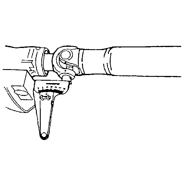
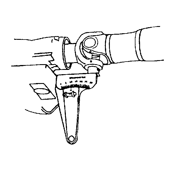

The front angle is considered the odd U-joint because this angle does not have another joint to provide cancellation. The rear working angle (6) and the middle working angle (7) act as a pair of U-joints in order to cancel each other out, as in the one-piece propeller shaft systems. Because of this condition, keep the working angle of the odd U-joint (8) at or under 1/2 degree.
Keep the working angle of this odd joint to a minimum so that there are not any great fluctuations in speed that need to be canceled out. The front joint is used as the odd joint because the front joint angle does not change with suspension bounce, rebound, or axle windup. For this reason, think of the front propeller shaft of a two-piece system as an extension of the transmission output shaft.
Evaluation
The working angle is within tolerance, following the rule that the working angle of an odd joint in a two-piece joint system is 1/2 degree or less. Notice that in each of the good examples the front working angle (FWA) is 1/2 degree or less and is treated as a separate joint. The middle working angle (MWA) and the rear working angle (RWA) are subtracted. The difference (DIFF) is 1/2 degree or less. The middle and the rear joints may cancel each other.
