Tools Required
J 8037 Ring Compressor
- Lubricate the following components with engine oil:
- Ensure that the piston ring end gaps are staggered equally around the piston.
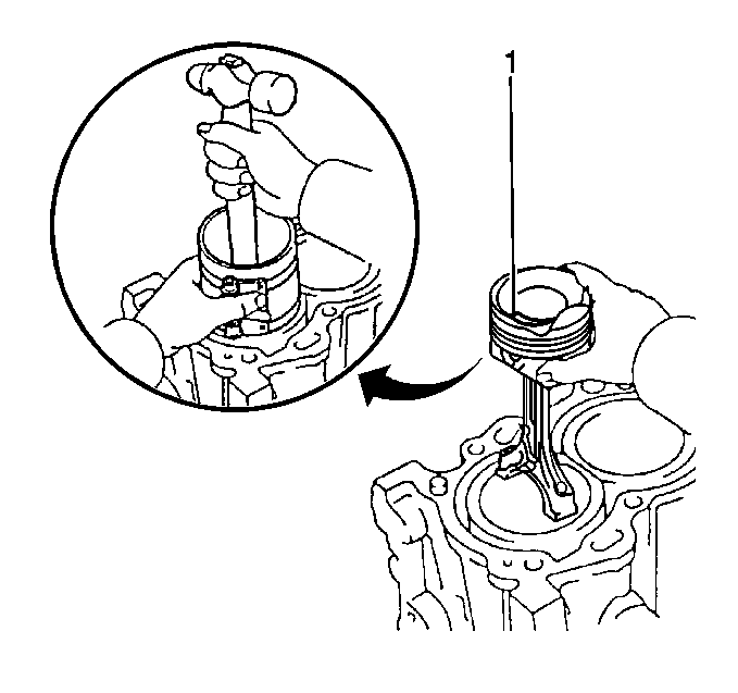
- Install the piston so that the mark on the top of the piston (1) faces the front of the engine.
- Install the upper connecting rod bearing to the connecting rod.
- Install a J 8037 over the piston, ensuring it sits firmly against the cylinder block until all of the piston rings have entered the cylinder bore.
- Install the piston assembly into its matching cylinder bore.
- Guide the connecting rod into place on the crankshaft.
- Gently tap the piston into its cylinder bore with a hammer handle.
- Install the lower connecting rod bearing to the connecting rod cap.
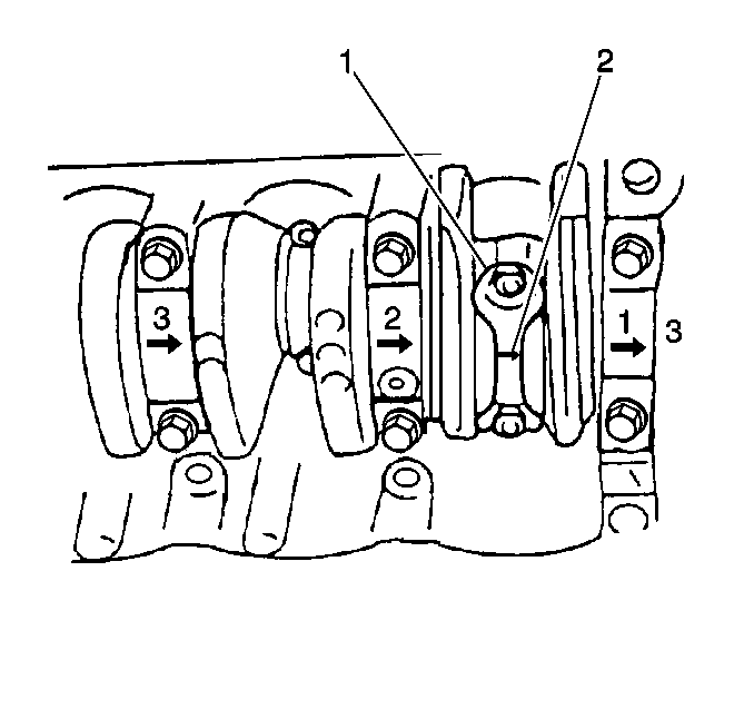
- Install the connecting rod cap (1) to its matching connecting rod with the arrow pointing towards the front of the engine. Secure with two connecting rod cap nuts.
- Pry the connecting rod back and forth in order to inspect for binding.
- Measure the connecting rod side clearance.

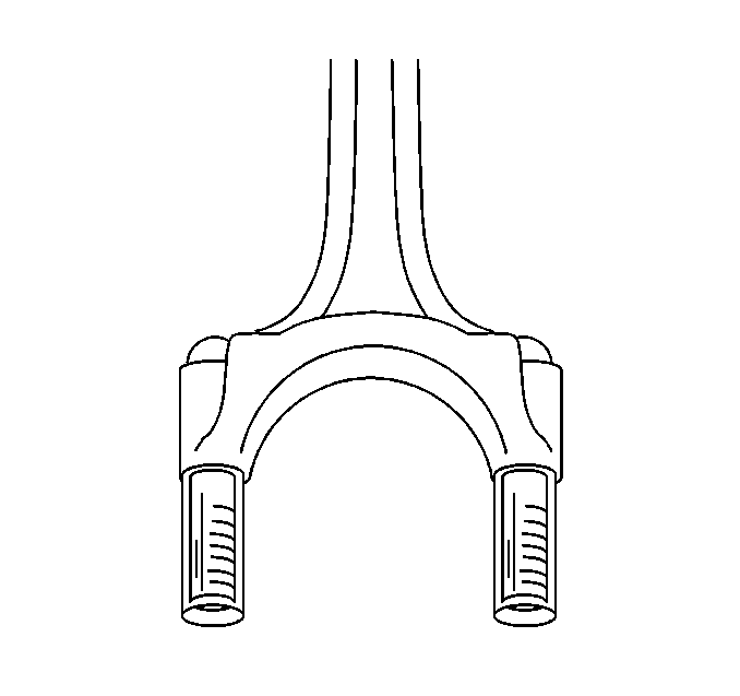
Notice: Install a piece of hose over the threads of the rod bolts. This is to prevent damage to the bearing journal, the cylinder walls, or the rod bolt threads when removing the connecting rod. Remove the hose after the connecting rod is in place.
| • | The pistons |
| • | The rings |
| • | The cylinder walls |
| • | The connecting rod bearings |
| • | The crankshaft journals |
Notice: Guide the lower connecting rod end carefully to avoid damaging the crankshaft journal.


Notice: Use the correct fastener in the correct location. Replacement fasteners must be the correct part number for that application. Fasteners requiring replacement or fasteners requiring the use of thread locking compound or sealant are identified in the service procedure. Do not use paints, lubricants, or corrosion inhibitors on fasteners or fastener joint surfaces unless specified. These coatings affect fastener torque and joint clamping force and may damage the fastener. Use the correct tightening sequence and specifications when installing fasteners in order to avoid damage to parts and systems.
Tighten
Tighten the connecting rod cap nuts to 45 N·m (33 lb ft).

Standard Connecting Rod Side Clearance
0.25-0.40 mm (0.0099-0.0157 in)
Maximum Connecting Rod Side Clearance
0.45 mm (0.0177 in)
