Wiper System Description
The windshield wiper system includes the following components:
| • | The wiper motor linkage |
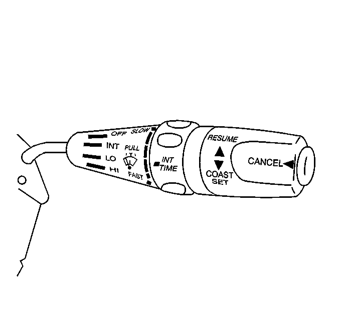
| • | The windshield wiper/washer switch lever |

The wiper/washer switch lever controls the wiper system. The switch
lever is located on the right side of the steering column. The switch lever
is not available as a individual component and must be serviced as an assembly
as part of the inflatable restraint module coil. Refer to
Inflatable Restraint Steering Wheel Module Coil Replacement
in
SIR.
The wiper circuit ensures that the wiper blades will automatically return
to the normal park position when the wiper switch lever is moved to OFF.
Interval (Pulse) System Operation
With the front wiper washer switch in the INT position, battery voltage
applies to the following components:
| • | The Intermittent Controller |
| • | The low side of the front wiper motor. |
The length of the delay time between sweeps is controlled by the INT
TIME switch setting. The INT TIME switch contains a variable resistor which
is connected to the Intermittent Controller IC. The delay between sweeps
is adjustable from SLOW, approximately 12 seconds, to FAST, approximately
4 seconds.
Low Speed System Operation
With the ignition switch in the ON or the START position and the front
wiper/washer switch in the LO position, battery voltage applies through the
following components:
| • | The LO contacts of the front wiper/washer switch |
| • | The low side of the front wiper motor |
Since the front wiper motor permanently grounds at G104, the motor operates
at low speed as long as the switch remains in the LO position. When the switch
is placed in the OFF position, the pawl and switch assembly provides
voltage to the motor until the wipers are in the park position.
High Operation
With the ignition switch in the ON or the START position and the front
wiper/washer switch in the HI position, battery voltage applies through the
following components:
| • | The HI contacts of the front wiper/washer switch |
| • | The high side of the front wiper motor |
Since the front wiper motor permanently grounds at G104, the motor
operates at high speed as long as the switch remains in the HI position.
When the switch is placed in the OFF position, the pawl and switch assembly
provides voltage to the motor until the wipers are in the park position.
Washer System Description
The windshield washer system includes the following components:
| • | The washer solvent container |
| • | The washer pump which is attached to the washer solvent container |
| • | The washer nozzle hoses |
| • | The windshield wiper/washer switch |
The washer solvent container is mounted on the left fender, behind the
left headlamp.
Washer System Operation
With the ignition switch in the ON or the START position, actuate the
windshield washer system by pulling the windshield wiper/washer switch lever
toward the driver. When the switch lever is pulled back, battery voltage
applies through the wash switch contacts to the front washer pump. The front
washer pump permanently grounds at G104 and will operate as long as the
wash switch is engaged. In order to initiate wiper operation, battery voltage
is also applied to the OFF contacts of the front wiper/washer switch
through these components:
| • | The Intermittent Controller IC |
This action applies voltage to the low side of the front wiper motor.
The front wiper motor permanently grounds at G104. The motor will continue
to operate in LO as long as the wash switch is engaged.
The front wiper motor pawl and switch will engage as the motor turns,
and the contacts will remain closed until the wipers are in the park position.
While the pawl and switch contacts are closed, voltage applies to the low
side of the front wiper motor through these components:
| • | The OFF contacts of the front wiper/washer switch |
| • | The front wiper motor pawl and switch contacts |
This action allows the wipers to complete at least one sweep after the
wash switch has been released.

