Catalytic Converter Replacement 4.2L Engine
Removal Procedure
- Raise the vehicle. Refer to Lifting and Jacking the Vehicle .
- Remove the heated oxygen sensor (H2OS). Refer to Heated Oxygen Sensor 2 Replacement .
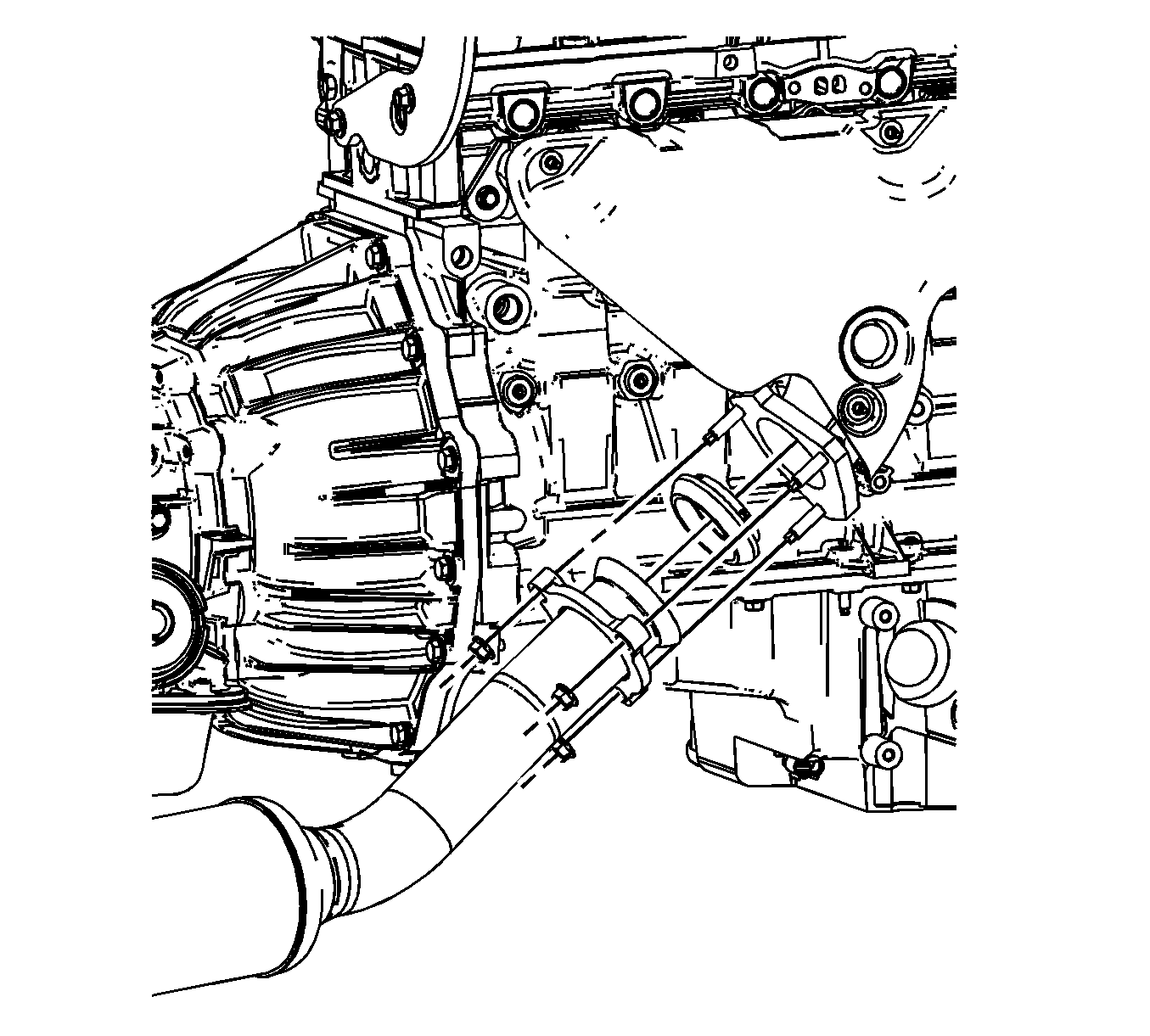
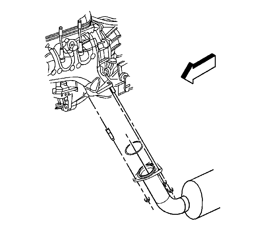
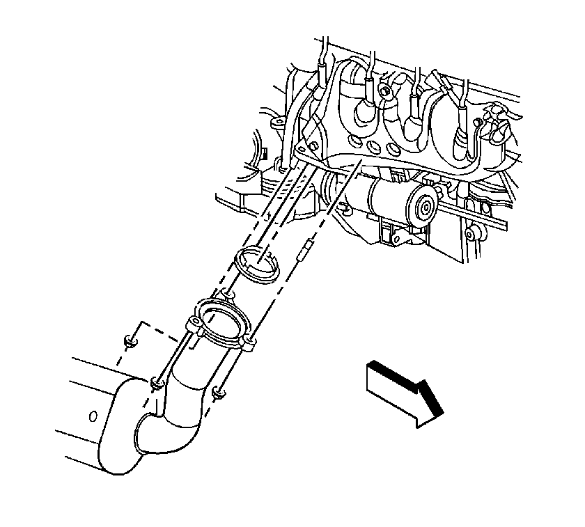
- Remove the nuts that secure the catalytic converter pipe to the exhaust manifold.
- Discard the old exhaust seal. Do NOT reuse the seal.
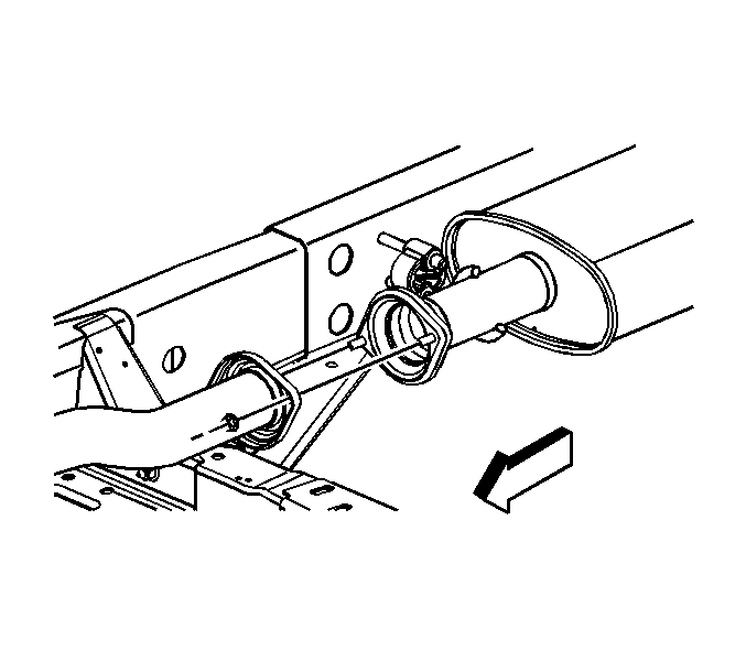
- Remove the nuts that secure the catalytic converter pipe to the muffler.
- Remove the transmission mount. Refer to Transmission Mount Replacement .
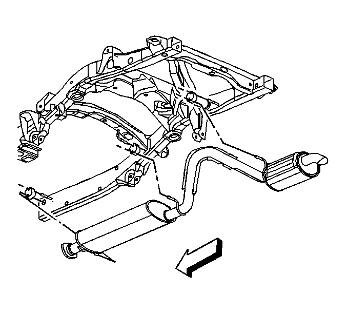
- Remove the catalytic converter pipe from the vehicle.
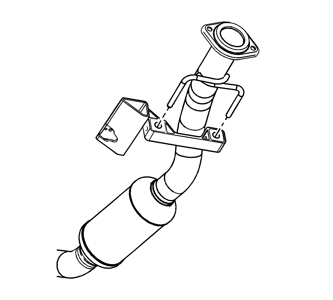
- Remove the exhaust hanger from the catalytic converter pipe.
Installation Procedure
- Install the exhaust hanger to the catalytic converter pipe.
- Install the catalytic converter pipe to the vehicle.
- Install the transmission mount. Refer to Transmission Mount Replacement .
- Install the converter pipe to the muffler.
- Hand thread both nuts evenly until they contact the exhaust flange.
- Install the converter pipe to the exhaust manifold with a NEW exhaust seal.
- Hand thread the nuts evenly against the exhaust flange until the pipe is secure.
- Install the H2OS. Refer to Heated Oxygen Sensor 2 Replacement .
- Lower the vehicle.


Notice: Use the correct fastener in the correct location. Replacement fasteners must be the correct part number for that application. Fasteners requiring replacement or fasteners requiring the use of thread locking compound or sealant are identified in the service procedure. Do not use paints, lubricants, or corrosion inhibitors on fasteners or fastener joint surfaces unless specified. These coatings affect fastener torque and joint clamping force and may damage the fastener. Use the correct tightening sequence and specifications when installing fasteners in order to avoid damage to parts and systems.
Important: The exhaust flange nuts must be tightened evenly to align the joint and prevent exhaust leaks.
Tighten
Tighten the nuts to 45 N·m (33 lb ft).
Important: Do NOT reuse the old exhaust seal. ALWAYS replace the exhaust seal to prevent exhaust leaks.

Tighten
Tighten the nuts to 50 N·m (37 lb ft).
Catalytic Converter Replacement 5.3L Engine
Removal Procedure
- Raise and suitably support the vehicle. Refer to Lifting and Jacking the Vehicle in General Information.
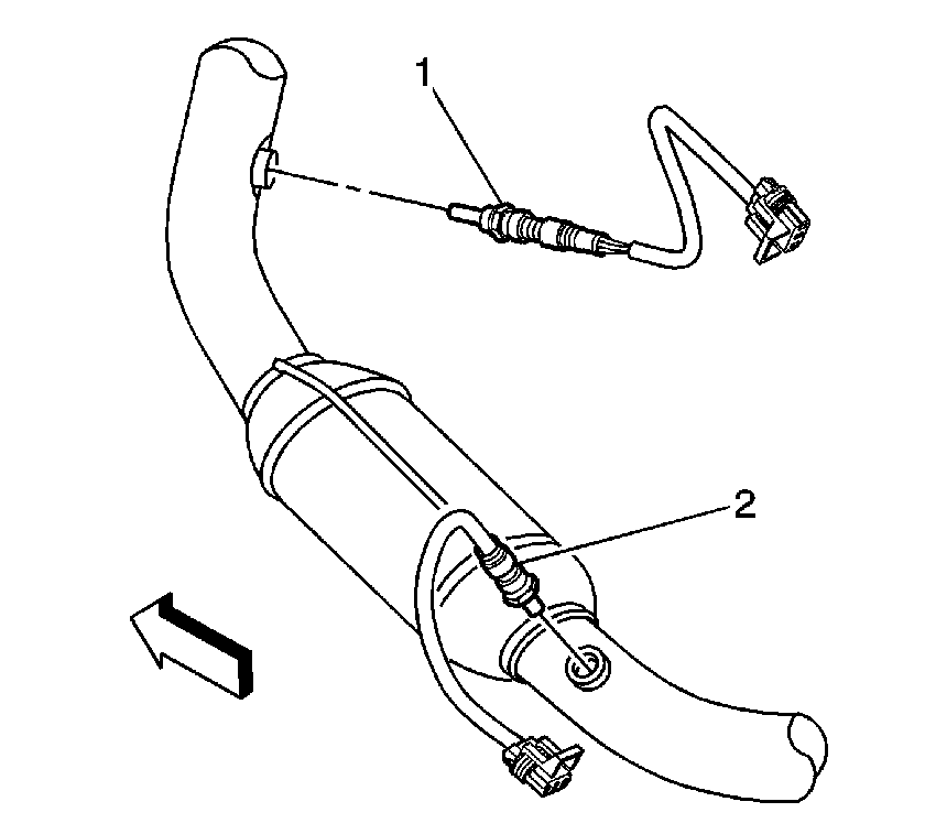
- Unscrew both front heated oxygen sensor (HO2S) sensors (1) from the catalytic converter.
- Unscrew both rear HO2S sensors (2) from the catalytic converter.
- Remove the rear propeller shaft. Refer to Rear Propeller Shaft Replacement in Propeller Shaft.
- If vehicle is equipped with RPO (NNK), remove the fuel tank. Refer to Fuel Tank Replacement in Engine Controls.
- If equipped with four wheel drive (4WD), Remove the front propeller shaft. Refer to Front Propeller Shaft Replacement in Propeller Shaft.
- Support the transmission with a transmission jack.
- Remove the transmission support. Refer to Transmission Support Replacement in Frame and Underbody.
- Remove the exhaust muffler nuts.
- Separate the exhaust hanger insulators from the exhaust system and position the exhaust system rearward for additional clearance.
- Remove the left exhaust manifold pipe nuts.
- Remove the right exhaust manifold pipe nuts.
- Raise the transmission with the transmission jack for additional catalytic converter pipe clearance.
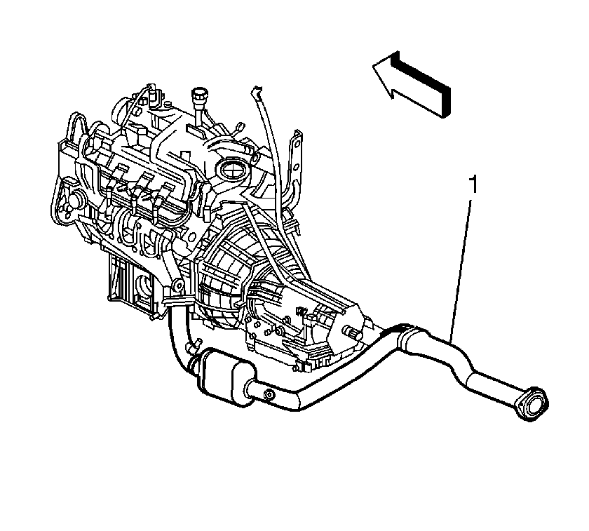
- Tilt the catalytic converter (1) in order to lower the left side catalytic converter pipe below the vehicle frame. Rotate the catalytic converter outlet pipe toward the left side of the vehicle to gain the necessary clearance for the right side catalytic converter pipe to clear the vehicle frame. Remove the catalytic converter (1) from the vehicle.
Notice: Refer to Heated Oxygen and Oxygen Sensor Notice in the Preface section.
Notice: Refer to Excessive Force and Oxygen Sensor Notice in the Preface section.

Installation Procedure
- Install the catalytic converter (1) in reverse order of removal by starting with the catalytic converter outlet pipe angled toward the left side of the vehicle and positioning the right side catalytic converter pipe above the frame. Rotate the catalytic converter outlet pipe toward the rear of the vehicle and lift the left side catalytic converter pipe up above the frame. Then position the catalytic converter (1) to the exhaust manifolds.
- Install the exhaust hanger insulators to the exhaust system.
- Install the exhaust muffler nuts. Ensure the catalytic converter is held in the installed position before tightening the nuts.
- Install the right exhaust manifold pipe nuts. Ensure the catalytic converter is held in the installed position before tightening the nuts.
- Install the left exhaust manifold pipe nuts.
- If removed, install the fuel tank. Refer to Fuel Tank Replacement in Engine Controls.
- Install the transmission support. Refer to Transmission Support Replacement in Frame and Underbody.
- Remove the transmission jack.
- If equipped with 4WD, install the front propeller shaft. Refer to Front Propeller Shaft Replacement in Propeller Shaft.
- Install the rear propeller shaft. Refer to Rear Propeller Shaft Replacement in Propeller Shaft.
- If reinstalling the old sensors, coat the threads with anti-seize compound GM P/N 12377953, or equivalent.
- Install both front HO2S sensors (1) to the catalytic converter.
- Install both rear HO2S (2) to the catalytic converter.
- Lower the vehicle.


Notice: Refer to Fastener Notice in the Preface section.

Tighten
Tighten the nuts to 45 N·m (33 lb ft).

Tighten
Tighten the nuts to 50 N·m (37 lb ft).

Tighten
Tighten the nuts to 50 N·m (37 lb ft).
Important: A special anti-seize compound is used on the HO2S threads. The compound consists of liquid graphite and glass beads. The graphite tends to burn away, but the glass beads remain, making the sensor easier to remove. New, or service replacement sensors already have the compound applied to the threads. If the sensor is removed from an exhaust component and if for any reason the sensor is to be reinstalled, the threads must have anti-seize compound applied before the reinstallation.
Notice: Refer to Component Fastener Tightening Notice in the Preface section.

Important: If the HO2S sensor is connected to the main wiring harness during installation. Rotate the HO2S sensor several turns counterclockwise before threading the HO2S sensor into the catalytic converter. This action of initially reverse winding of the pigtail wires will prevent a condition where the HO2S sensor pigtail wires become severely twisted or binding once the HO2S sensor is installed into the catalytic converter.
Tighten
Tighten the sensor to 42 N·m (31 lb ft).
Tighten
Tighten the sensor to 42 N·m (31 lb ft).
