SMU - Revised Secondary Air Injection Pipe Replacement Procedure

| Subject: | Revised Secondary Air Injection Pipe Replacement Procedure |
| Models: | 2004-2006 Buick Rainier |
| 2004-2006 Chevrolet TrailBlazer |
| 2004-2006 GMC Envoy |
| with 4.2L Inline Six Cylinder Engine (VIN S -- RPO LL8) |
This bulletin is being issued to revise the Secondary Air Injection Pipe Replacement Procedure - Manual procedure in the Engine Controls-4.2L sub-section of the Service Manual. Please replace the current information in the Service Manual with the following information.
The following information has been updated within SI. If you are using a paper version of this Service Manual, please make a reference to this bulletin on the new Secondary Air Injection Pipe Replacement Procedure.
Secondary Air Injection Pipe Replacement (2004-2005 Model Year Vehicles)
Removal Procedure
- Raise the vehicle. Refer to Lifting and Jacking the Vehicle .
- Disconnect both the air inlet and air outlet pipe from the secondary air injection reaction (AIR) pump.
- Remove the air inlet and air outlet pipe retaining clip from the fuel rail.
- Lower the vehicle.
- Remove the intake manifold. Refer to Intake Manifold Replacement.
- Remove the number 6 ignition coil. Refer to Ignition Coil Replacement .
- Disconnect the AIR hose from the air box.
- Disconnect the AIR hose from the solenoid valve.
- Remove the bolt and fir-tree fasteners securing the AIR pipe to the cylinder head.
- Remove the AIR hose assembly by rotating over the top of the engine.
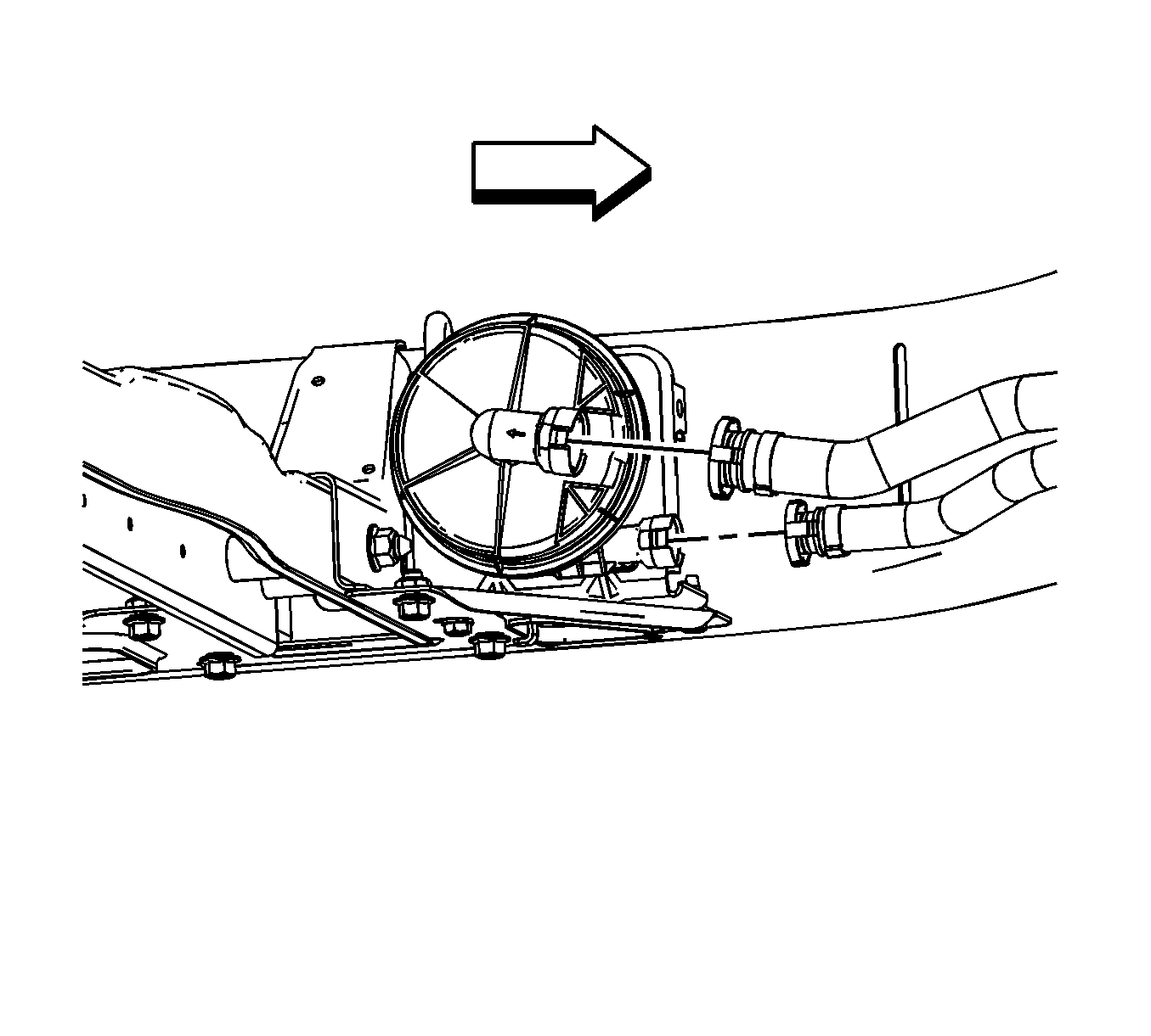
Important: It is not necessary to remove the throttle body to remove the intake manifold.
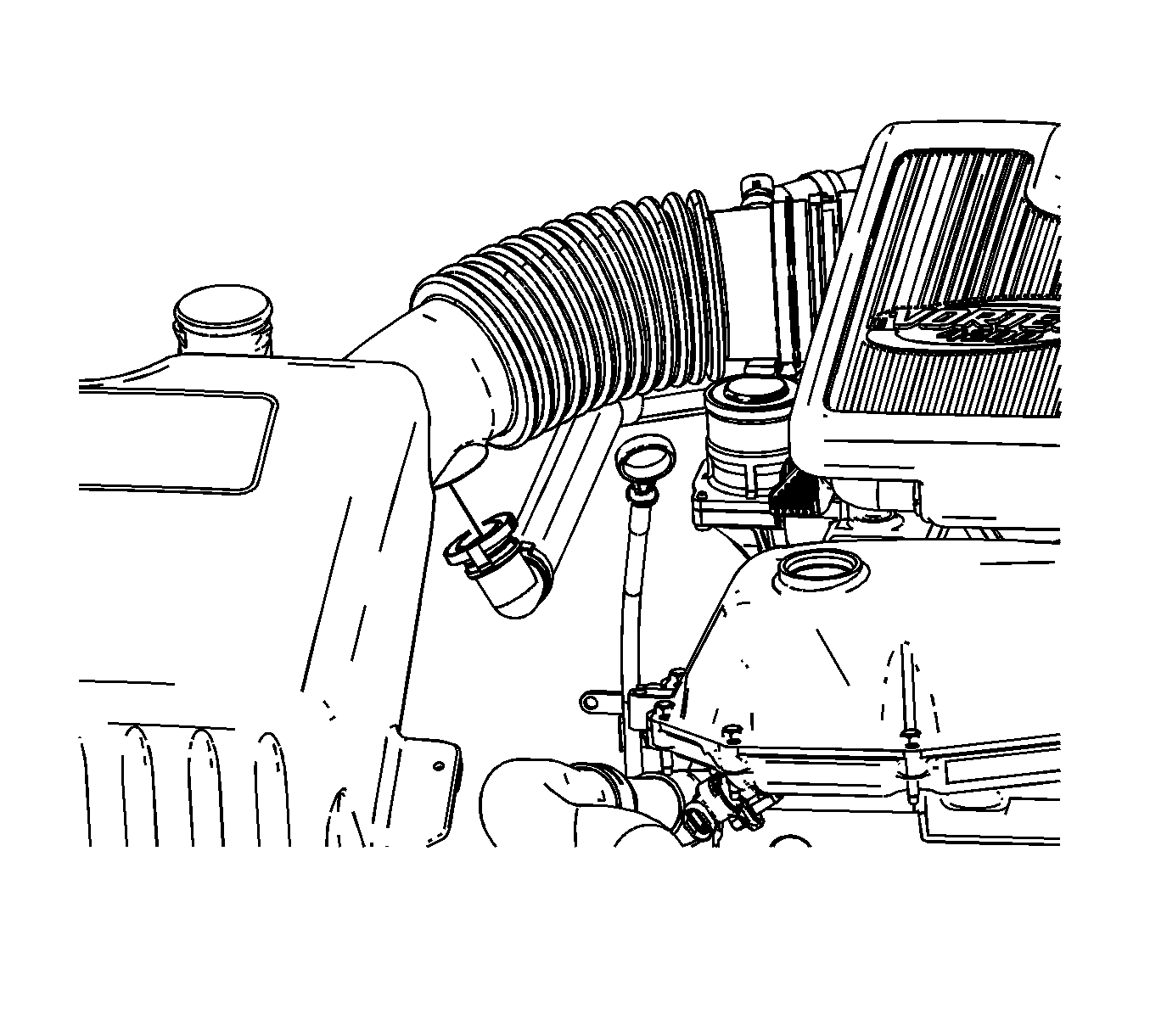
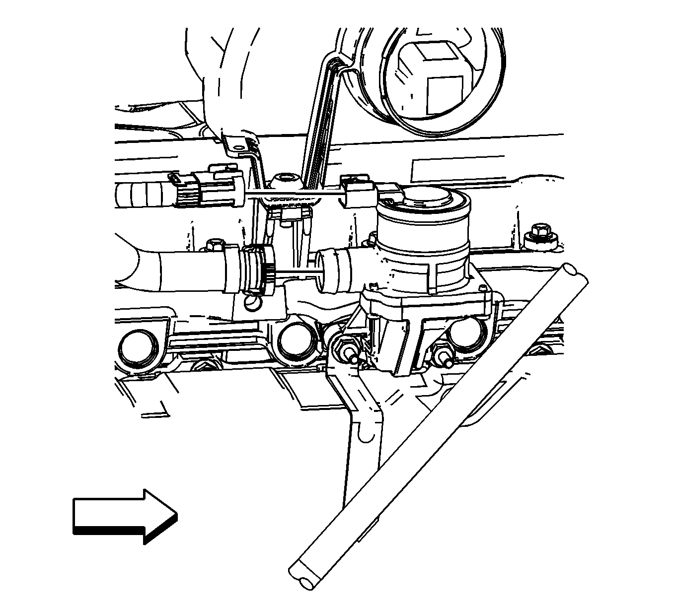
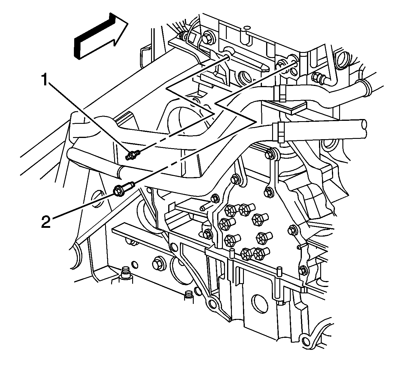
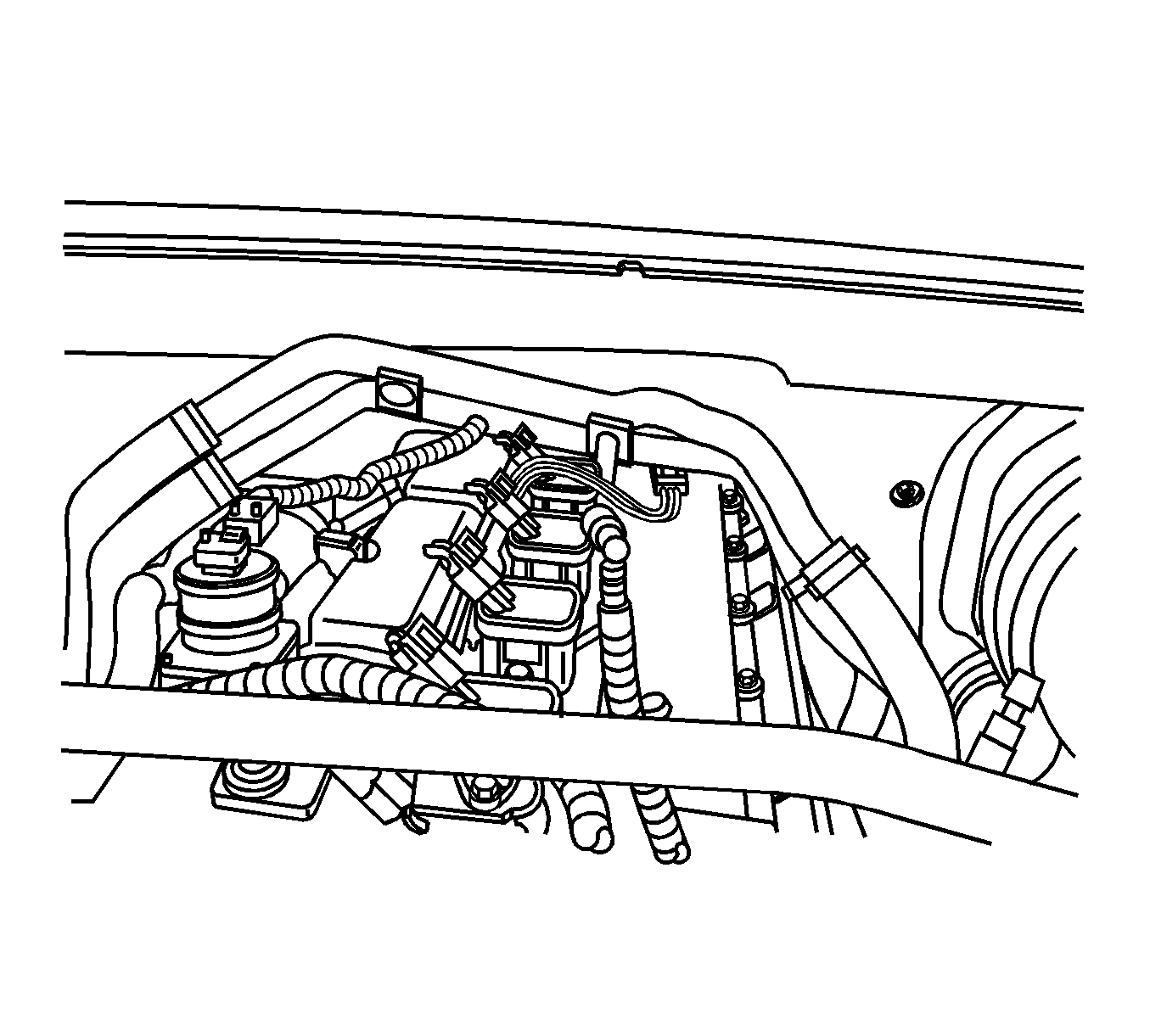
Installation Procedure
- Install the AIR hose assembly by rotating over the top of the engine.
- Add a drop of P/N 12345382 (Canadian P/N 10953489) to the bolt threads.
- Install the bolt and fir-tree fasteners securing the AIR pipe to the cylinder head. Tighten the bolt until fully seated.
- Connect the AIR hose to the air box.
- Connect the AIR hose to the solenoid valve.
- Install the intake manifold. Refer to Intake Manifold Replacement .
- Install the number 6 ignition coil. Refer to Ignition Coil Replacement .
- Raise the vehicle. Refer to Lifting and Jacking the Vehicle .
- Connect the air inlet and air outlet pipe retaining clip to the fuel rail.
- Connect both the air inlet and air outlet pipe to the AIR pump.
- Lower the vehicle.


Notice: Refer to Fastener Notice in Cautions and Notices.


Secondary Air Injection Pipe Replacement (2006 Model Year Vehicles)
Removal Procedure
- Raise the vehicle. Refer to Lifting and Jacking the Vehicle .
- Disconnect both the air inlet and air outlet pipe from the secondary air injection reaction (AIR) pump.
- Remove the air inlet and air outlet pipe retaining clip from the fuel rail.
- Lower the vehicle.
- Remove the intake manifold. Refer to Intake Manifold Replacement .
- Remove the number 6 ignition coil. Refer to Ignition Coil Replacement.
- Disconnect the AIR hose from the air box.
- Disconnect the AIR hose from the solenoid valve.
- Disconnect the engine coolant temperature (ECT) sensor electrical connector.
- Remove the bolt and fir-tree fasteners securing the AIR pipe to the cylinder head.
- Remove the AIR hose assembly by rotating over the top of the engine.

Important: It is not necessary to remove the throttle body to remove the intake manifold.
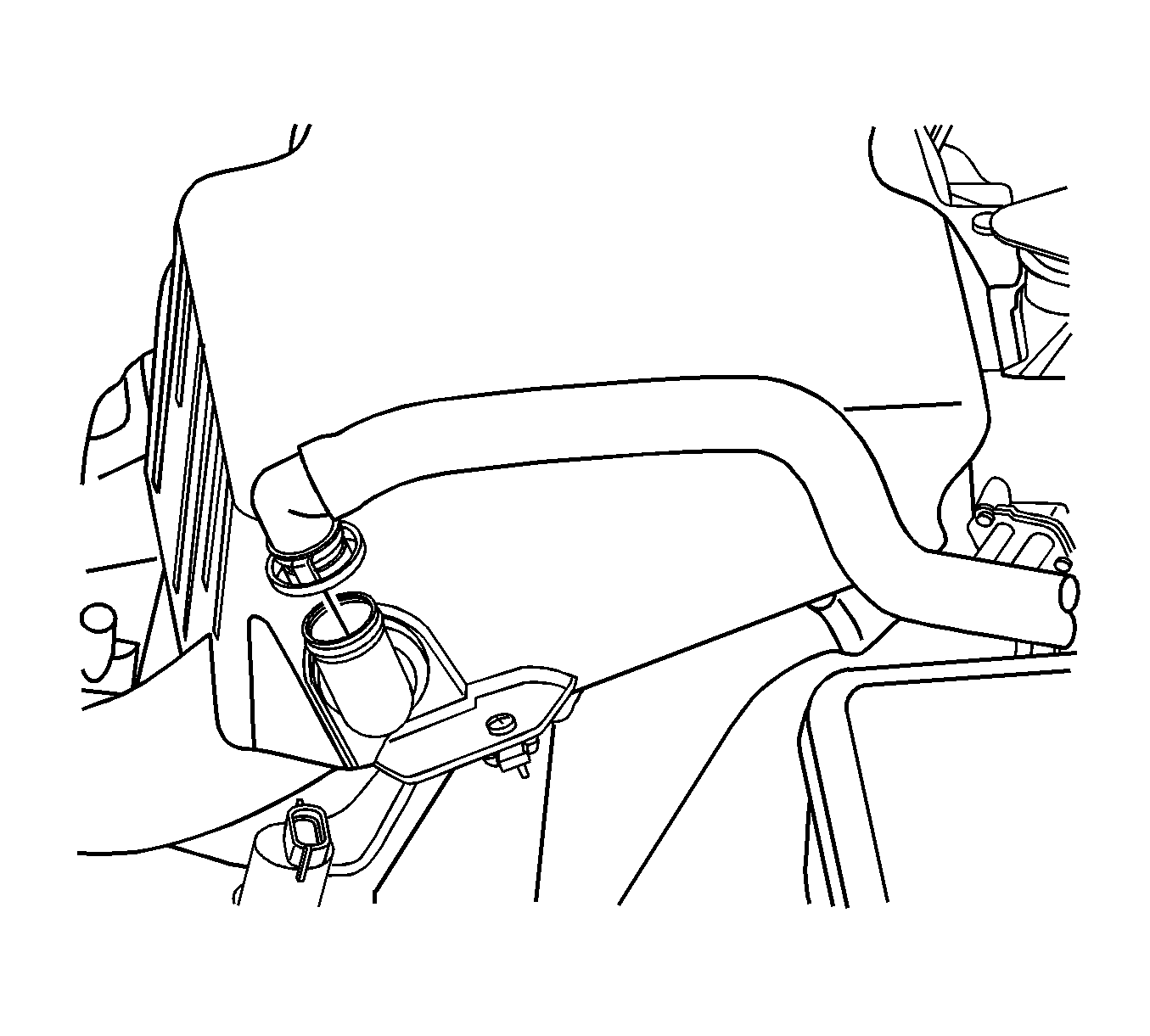

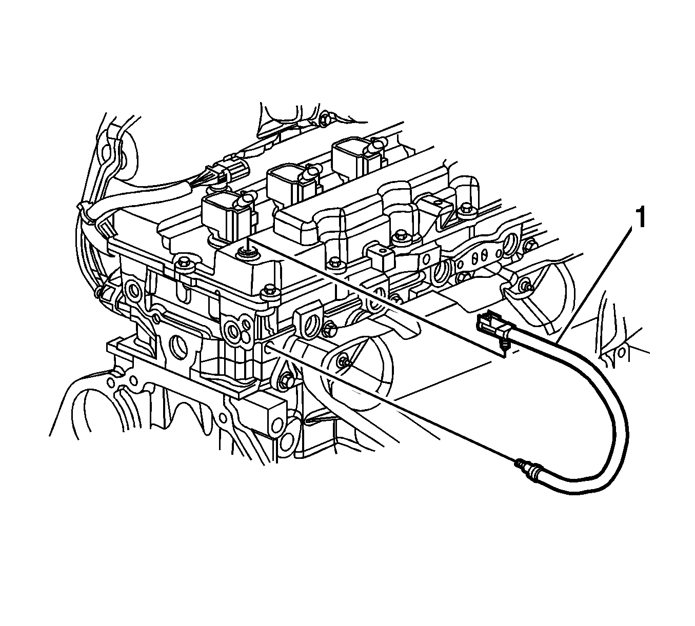


Installation Procedure
- Install the AIR hose assembly by rotating over the top of the engine.
- Add a drop of P/N 12345382 (Canadian P/N 10953489) to the bolt threads.
- Install the bolt and fir-tree fasteners securing the AIR pipe to the cylinder head. Tighten the bolt until fully seated.
- Connect the AIR hose to the air box.
- Connect the AIR hose to the solenoid valve.
- Connect the ECT sensor electrical connector.
- Install the intake manifold. Refer to Intake Manifold Replacement.
- Install the number 6 ignition coil. Refer to Ignition Coil Replacement.
- Raise the vehicle. Refer to Lifting and Jacking the Vehicle.
- Connect the air inlet and air outlet pipe retaining clip to the fuel rail.
- Connect both the air inlet and air outlet pipe to the AIR pump.
- Lower the vehicle.

Notice: Refer to Fastener Notice in Cautions and Notices.


Warranty Information
The warranty information reflects the revised service procedure above.
Labor Operation | Description | Labor Time |
|---|---|---|
J6117 | Pipe, SAI Manifold-Both - Replace | 2.3 hrs* |
*The existing labor operation time has been reduced. The new time is shown above. The next update of the Labor Time Guide will reflect this change.
