Removal Procedure
Caution: Refer to Approved Equipment for Collision Repair Caution in the Preface section.
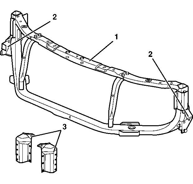
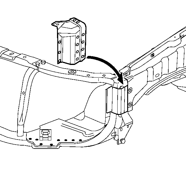
Important: The radiator support assembly is made from mild steel hydroformed tube which is welded to the front structure. The radiator support assembly is serviced as a complete assembly. The bolt-on portion of the upper tie bar (1) as well as the left and the right fascia support brackets (2) are a part of the radiator assembly. If the damage is limited to these parts they can be ordered and replaced individually. Replacement of the radiator support assembly requires removal of the upper fender rails. Upper fender rail service extensions (3) are included with the radiator support assembly for efficient installation. If the damage permits, locate and cut off the front portion of the upper rails along the die mark indicators and install the replacement upper fender rail service extensions. This procedure must be performed on both sides of the vehicle. Left side only is shown.
- Remove all of the related panels and components.
- Restore as much of the damage as possible back to the factory specifications.
- Note the location and remove the following as necessary:
- Locate the 2 die-mark indicators on the upper fender rail.
- Apply the masking tape for the cut location over the die-marks and across the top of the upper rail.
- Cut the upper fender rail along the front edge of the tape line.
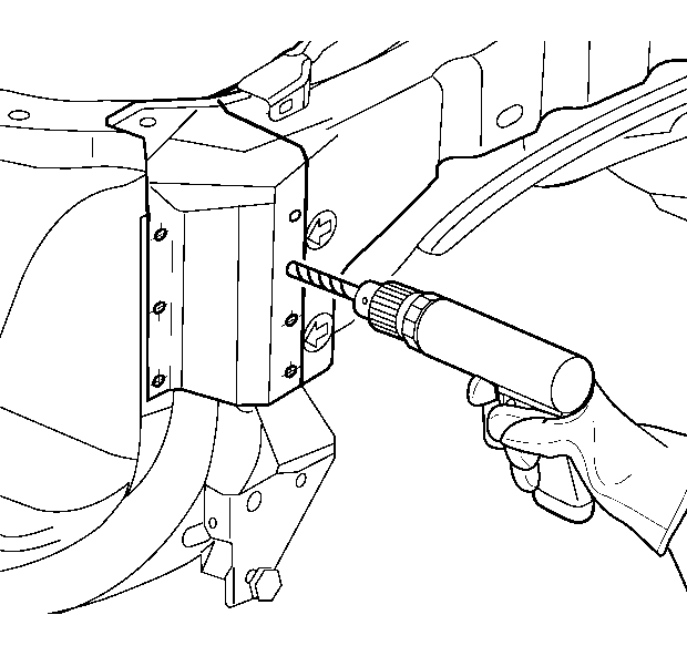
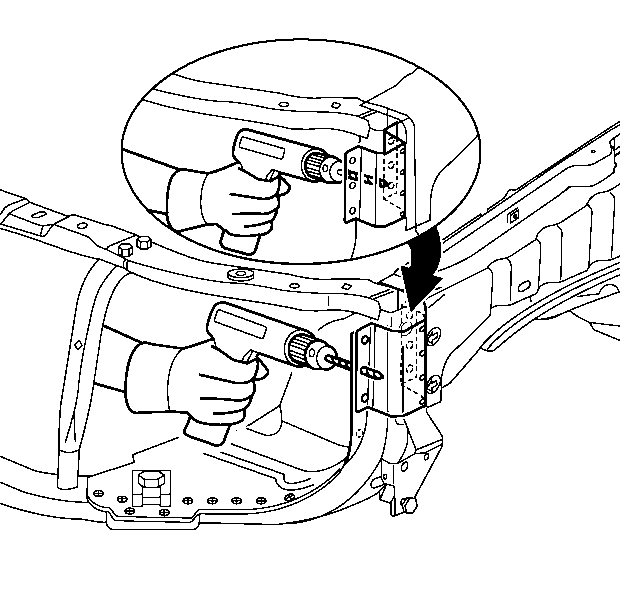
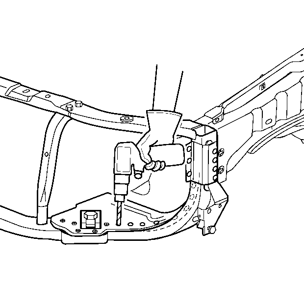
- Locate and drill out all of the factory welds in the upper fender rail in front of the cut location.
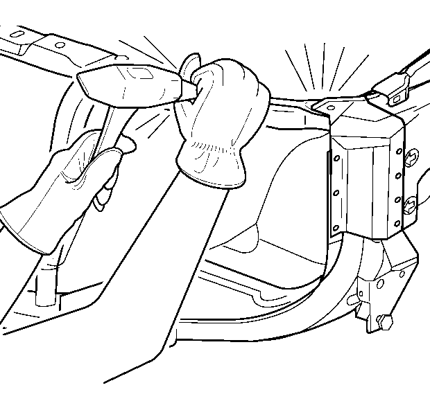
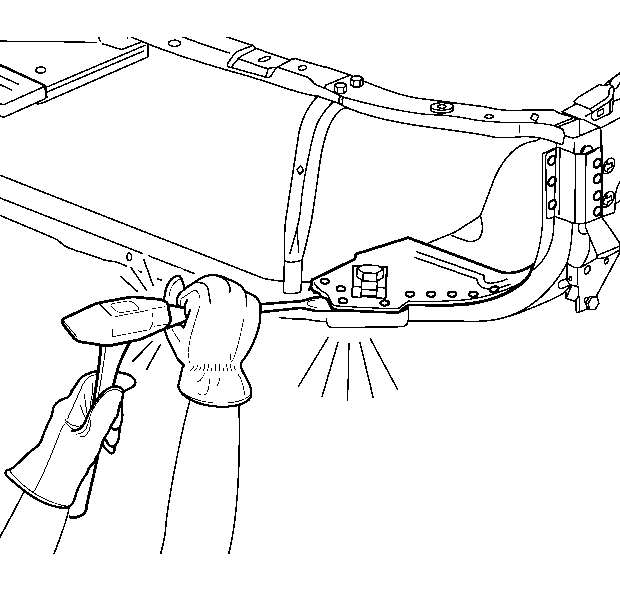
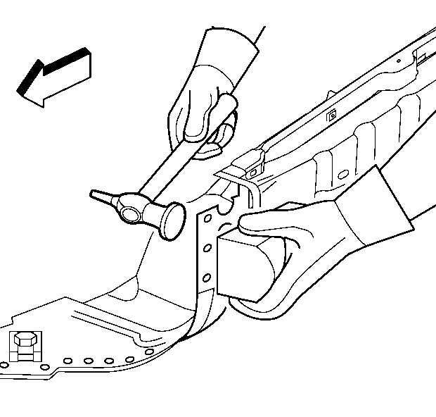
- If necessary, use a chisel in order to separate the upper fender rail extension from the radiator support.
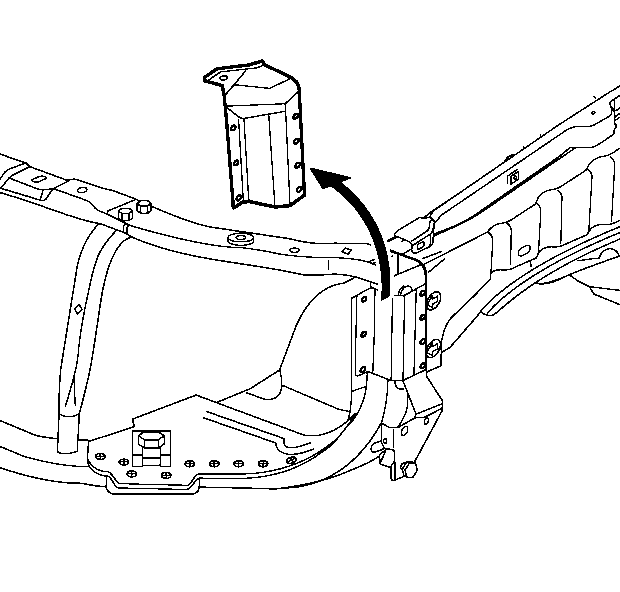
- Remove the upper fender rail extension.
- Locate and drill out all of the factory welds in the upper wheelhouse area.
- Locate and drill out all of the factory welds along the wheelhouse extension.
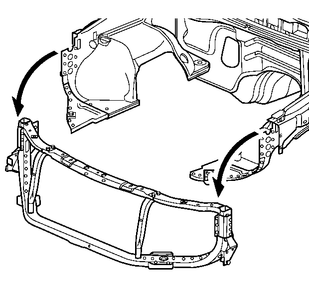
- If necessary, use a chisel in order to separate the radiator support from the vehicle.
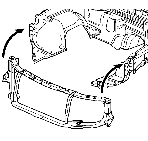
- Remove the damaged radiator support.
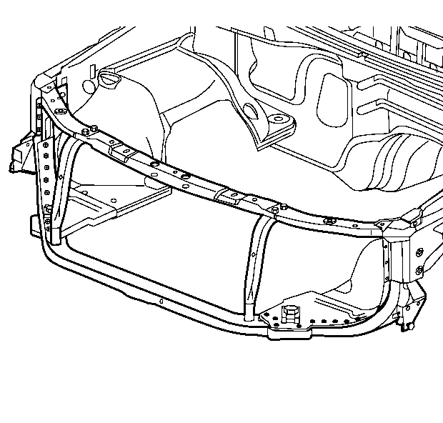
| • | The sealers |
| • | The sound deadeners |
| • | The anti-corrosion materials |
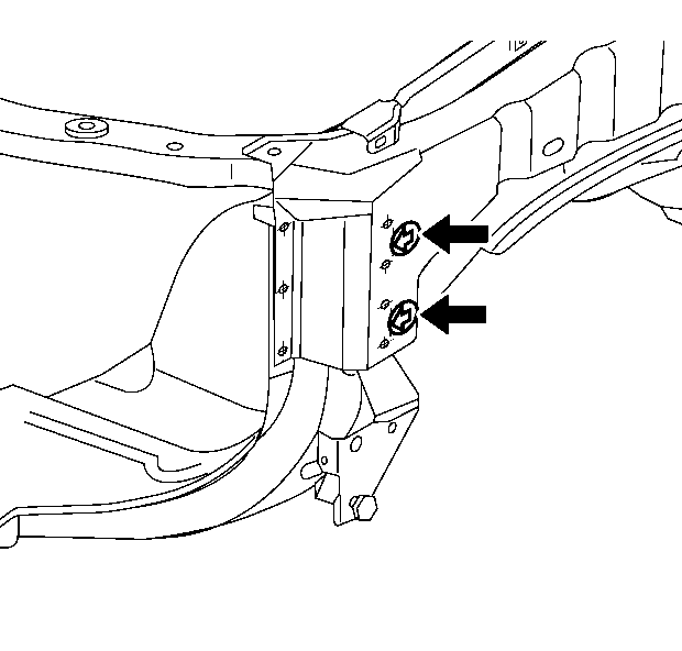
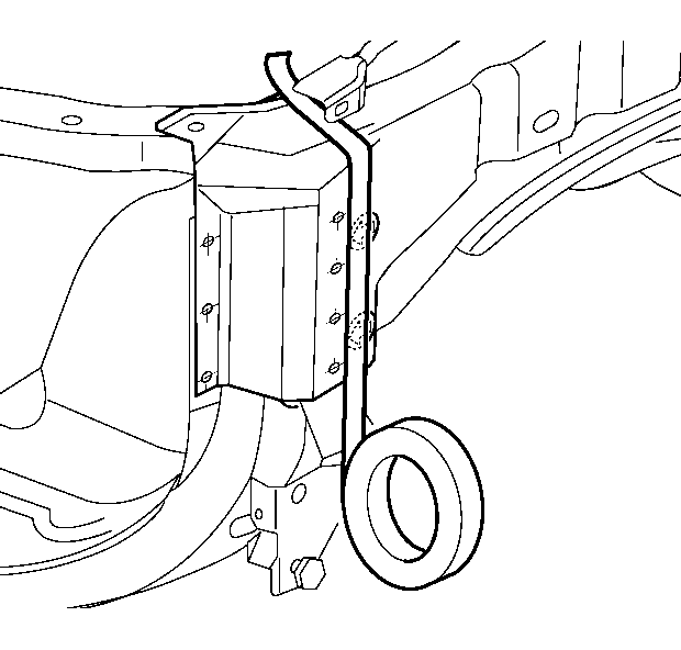
Important: The edge of the masking tape must line up with the point of each die-mark arrow.
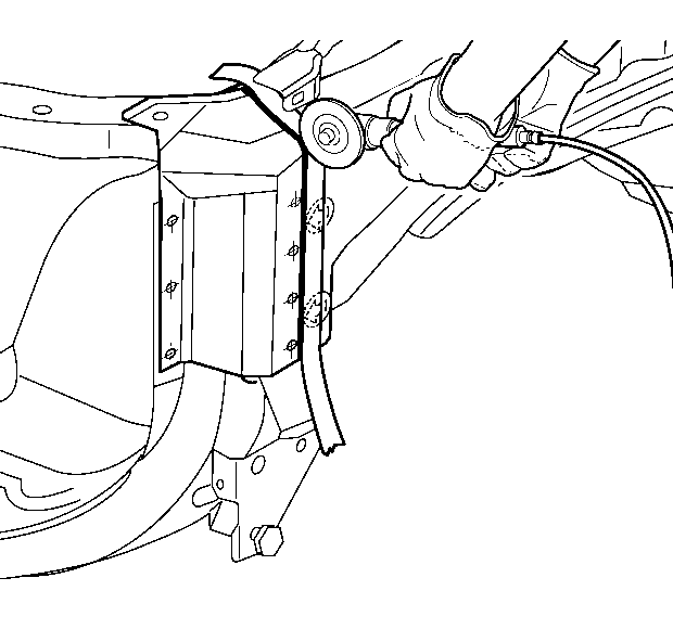
Important: The tape edge facing the front of the vehicle is the proper location.
Installation Procedure
- Prepare all of the mating surfaces as necessary.
- Apply GM-approved Weld-Thru Coating or equivalent to all mating surfaces. Refer to Anti-Corrosion Treatment and Repair .
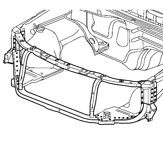
- Position and align the radiator support using 3-dimensional measuring equipment.
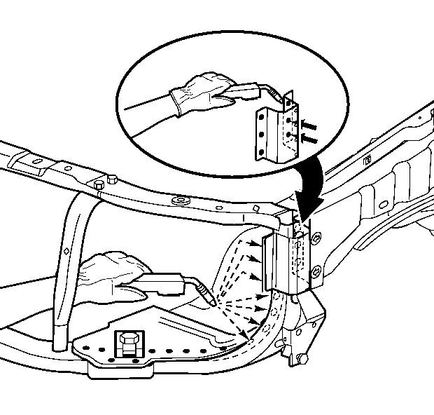
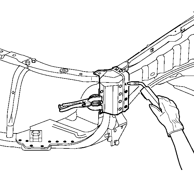
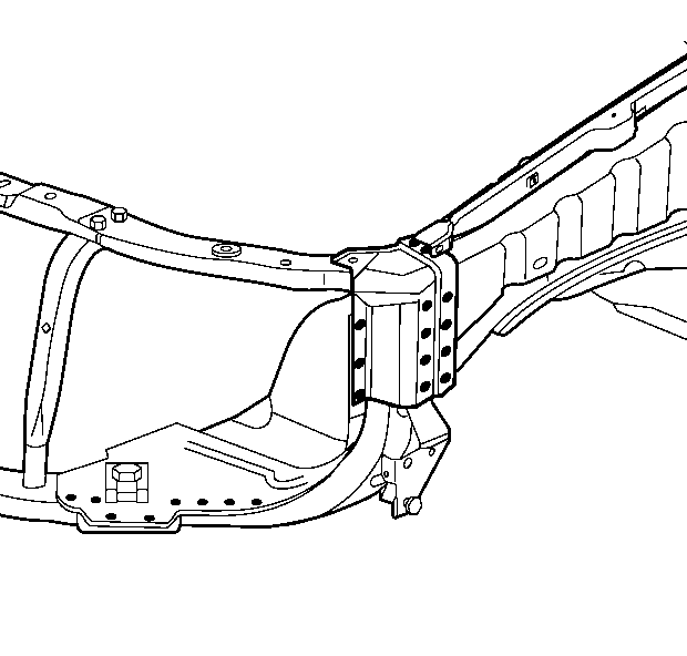
- Plug weld accordingly with the frequent measurements to ensure the proper positioning.
- Position and align the upper fender rail extension using the three-dimensional measuring equipment.
- Plug weld accordingly with frequent measurements to ensure the proper positioning.
- Clean and prepare all of the welded surfaces.
- Apply the following as necessary:
Important: In any area with excessive damage, space the plug weld holes every 40 mm (1½ in) apart.
| • | Apply the sound deadening materials. |
| • | Apply an approved anti-corrosion primer. |
| • | Apply the sealers and refinish as necessary. |
