For 1990-2009 cars only
Special Tools
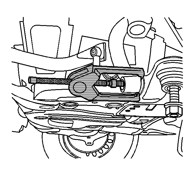
J 24319-B Steering Linkage and Tie Rod Puller
Removal Procedure
- Raise and support the vehicle. Refer to Lifting and Jacking the Vehicle .
- Remove the tire and wheel. Refer to Tire and Wheel Removal and Installation .
- Support the lower control arm with an appropriate jack stand.
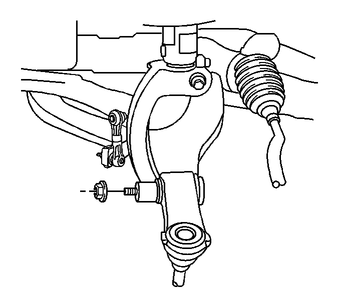
- Remove the shock module yoke to lower control arm mounting nut.
- Using the J 24319-B , remove the shock module yoke from the lower control.
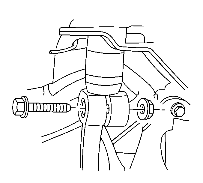
- Remove the shock module yoke to shock absorber bolt and nut.
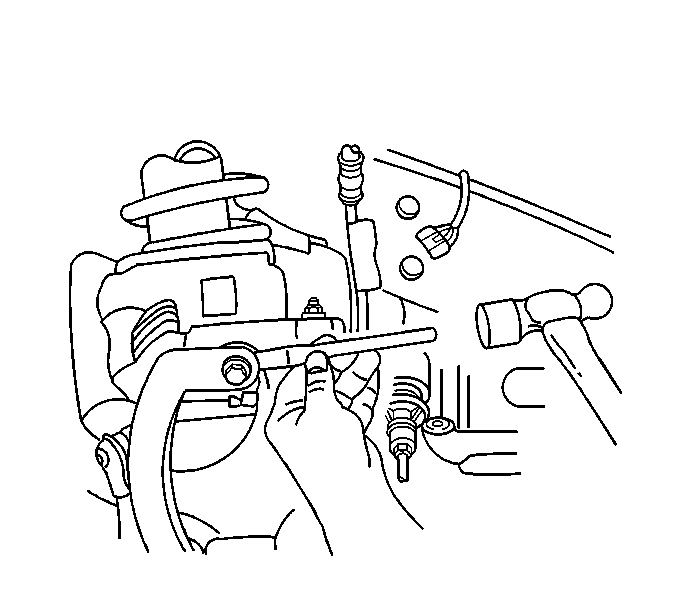
- Using a flat bladed tool, spread the shock module yoke at the bolt.
- Remove the shock module yoke from the shock absorber.

Important: The lower control arm must be supported so that the ball is not over extended.


Installation Procedure
- Install the shock module yoke to the lower control arm stud and shock absorber.
- Install the shock module yoke to shock absorber bolt and nut.
- Install the shock module yoke to lower control arm mounting nut.
- Remove the jack stand from the lower control arm.
- Install the tire and wheel. Refer to Tire and Wheel Removal and Installation .
- Lower the vehicle.

Important: Ensure that the shock absorber is fully seated in the yoke.
Notice: Refer to Fastener Notice in the Preface section.
Important: The bolt that secures the shock absorber to the shock absorber yoke moves freely to ensure the proper alignment of the shock absorber yoke to the lower control arm.
Tighten
Tighten the shock module yoke to shock absorber bolt to 70 N·m (52 lb ft).

Tighten
Tighten the shock module yoke to lower control arm mounting nut to 111 N·m (82 lb ft).
