| Subject: | EI07279 -- Horn Inoperative from Steering Wheel Horn Pad (Engineering Information) |
| Models: | 2006 Chevrolet TrailBlazer EXT |
| 2006-2008 Chevrolet TrailBlazer |
| 2006-2008 GMC Envoy, Envoy Denali |
| Attention: | Proceed with this bulletin ONLY if the customer has commented about this concern AND the EI number is listed in GMVIS, otherwise disregard the bulletin and proceed with diagnostics found in the published service information. THIS IS NOT A RECALL.
Refer to Service Bulletin 04-00-89-053A for more detail on the use of Engineering Information bulletins. |
This bulletin is being revised to update the diagnostic steps. Please discard Corporate Bulletin Number 07-08-54-001 (Section 08 -- Body & Accessories)
Condition
Important: If the horn does not work from the key fob horn button, disregard this bulletin and proceed with diagnosis/repair according to SI.
Some customers may comment that the horn is inoperative from the horn pad on the steering wheel.
Cause
GM Engineering is attempting to find the source of an open in the ground path through the steering column.
GM has a need to obtain information DURING diagnosis. Perform the following inspection/steps:
- Does the horn work by depressing the button(s) on the key fob?
| • | Yes -- proceed with step 2. |
| • | No -- do not proceed with this bulletin - diagnose and repair using information found in SI. |
- Depress the horn pad to see if the horn works.
| • | Yes -- rotate the steering wheel to one extreme of rotation. Test the horn pad operation every few degrees as you turn the wheel to the opposite extreme of rotation. Note any steering wheel position in which the horn does not operate. Proceed
with step 3. |
| • | No -- proceed with step 3. |
Caution : When performing service on or near the SIR components or the SIR wiring, the SIR system must be disabled. Refer to SIR Disabling and Enabling . Failure to observe the correct procedure could cause deployment of the
SIR components, personal injury, or unnecessary SIR system repairs.
- Remove the Inflatable Restraint Steering Wheel Module using the procedure found in Service Information. Does the horn work when the horn contacts are depressed?
| • | Yes -- Proceed with step 4. |
| • | No -- Verify that there are no steering wheel positions where the horn works and proceed to step 9. If the horn works in spots, go to step 4. |
- Rotate the steering wheel from extreme to extreme, testing horn operation every few degrees of rotation to see if a dead spot can be found. Are any dead spots present?
| • | Yes -- note the fact that inop condition is steering wheel position sensitive on the repair order. Proceed with step 5. |
| • | No -- proceed to step 9. |
- Remove the spring loaded contact on the end of the red wires and examine the contact surface for corrosion. Clean the contact and reinstall. Are there still dead spots in the horn pad operation when the steering wheel is rotated?
| • | Yes -- proceed with step 6. |
| • | No -- proceed with step 16. |
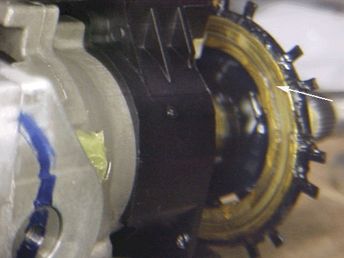
Turn Signal Cancel Cam:

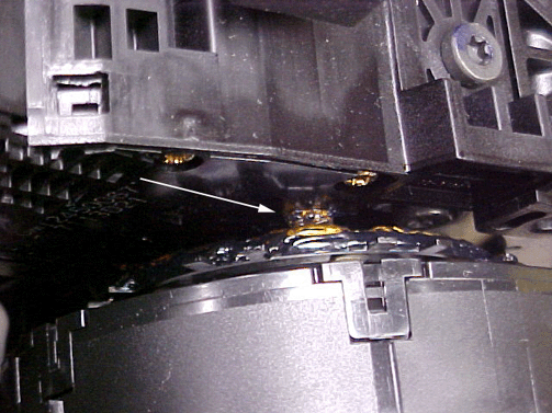
Turn Signal Switch Plunger Contact:

- Remove the steering column trim covers and look for signs of contamination between the turn signal cancel cam (refer to graphic) and the plunger contact on turn signal switch (refer to graphic). Also look for damage to the surface of the cancel cam. Remove
any contamination or replace the damaged cancel cam as necessary. Are there still dead spots in the horn pad operation when the steering wheel is rotated?
| • | Yes -- proceed to step 7. |
| • | No -- proceed to step 16. |
- Remove the turn signal switch assembly and reinstall. Are there still dead spots in the horn pad operation when the steering wheel is rotated?
| • | Yes -- proceed to step 8. |
| • | No -- proceed to step 16. |
- Replace the turn signal switch assembly and save the part for GM Engineering. Does the horn work properly at all steering wheel positions?
| • | Yes -- proceed to step 16. |
| • | No -- proceed with step 9. |
- Remove the left side IP insulator (refer to Instrument Panel Insulator Panel Replacement found in SI) so it can be moved aside enough to see the steering column.
- Depress the horn contacts in the steering wheel. Does the horn work?
| • | Yes -- proceed to step 16. |
| • | No -- proceed to step 11. |
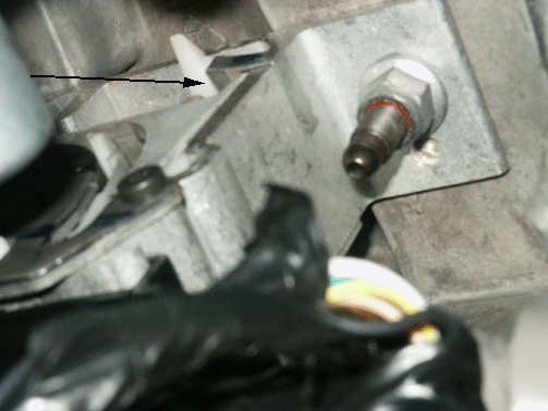
Horn Clip:

- Inspect the steering column through the insulator panel location. Note: The shaft from the steering wheel comes through a metal bracket. That bracket is surrounded by plastic, which is inside of another metal bracket. Look for a small metal clip (refer
to graphic above) that connects the inner bracket (inside the plastic) and the outer bracket. Is the clip present?
| • | Yes -- proceed to step 12. |
| • | No -- note the missing clip on the repair order. Proceed to step 15. |
- Without touching the clip, use a test light or ammeter to jumper between the red wires on the horn contact and the outer bracket on the steering column. Does the horn work when the jumper touches the outer bracket?
| • | Yes -- Remove the small clip and inspect for signs of corrosion and note findings on the repair order. Clean off any corrosion and reinstall the clip. Proceed to step 13. |
| • | No -- Proceed to step 14. |
- Does the horn work when the horn contact is depressed?
| • | Yes -- note on the repair order and proceed to step 16. |
| • | No -- proceed to step 14. |
- Jumper between other grounded points and the red horn wire. Does the horn work when jumpered to another ground?
| • | Yes -- note which ground enabled the horn to work. Proceed with step 15. |
| • | No -- refer to "Horn Inoperative" section in SI to diagnose which component in the circuit is causing the horn inop. Note on the repair order and make the necessary repairs. Proceed to step 16. |
- Complete the following steps to add a ground strap between the mounting bolts of the steering column.
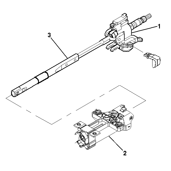
Steering Column Support Assembly:

| 15.2. | Refer to item number 2 in the graphic. This graphic shows the column support assembly. A closer look will reveal the four mounting holes of the column support assembly. |
| | Important:
| • | If a grounding strap cannot be obtained locally, one can be made by obtaining two eyelets that match the size of the column support bolts or studs and a 12 gauge (3.0 mm) wire. Cut the wire to the length needed in order to complete the circuit. |
| • | Some model year vehicles switched to column bracket and/or mount that may be isolated by rubber. It may be necessary to locate an alternate location to secure the ground wire to the column or column bracket in order to complete the circuit. |
|
| 15.3. | Add one (1) grounding strap from the column mount (use only one of the two upper mounting holes) to one of the two lower mounting holes in the steering column support assembly or other more appropriate grounding location from step 14. |
| 15.4. | Proceed with step 16. |
- Contact the engineer -- Dave Orth (248-676-1878)
to provide diagnostic results. If the engineer is not available to take the call, fax the front and back of the completed repair order to:
Warranty Information
For vehicles repaired under Engineering direction, use:
Labor Operation
| Description
| Labor Time
|
N9584*
| Horn Inop -- Engineering Information
| 1.3 hrs
|
* This labor operation number is for bulletin use only. This number will not be published in the Labor Time Guide.
|


