Use of Labor Operation Z6998 During Pre-Delivery Inspection (PDI)/PDI Instructions for RPO B4U on TrailBlazer SS Models

| Subject: | Use of Labor Operation Z6998 During Pre-Delivery Inspection (PDI) / PDI Instructions for RPO B4U on TrailBlazer SS Models |
| Models: | 2006-2009 Chevrolet TrailBlazer SS |
| with Sports Performance Package (RPO B4U) |
This bulletin is being revised to add the 2009 model year. Please discard Corporate Bulletin Number 06-00-89-039B (Section 00 -- General Information).
Warranty analysis has shown that additional charges for TrailBlazer SS-specific parts installed during pre-delivery inspection (PDI) are being handled using the incorrect and/or overlapping labor operations.
The only appropriate add time for PDI (excluding fluids) on the TrailBlazer SS is an add time of 0.3 hr to be used in conjunction with labor operation Z6998 for RPO B4U (equipment groups 1SS and 3SS). This includes the installation of the rear fascia closeout, the rear exhaust bracket and alignment, the driving lamp support brackets, and the front fender inserts. Do Not use additional labor operations to charge for the installation of these components. Instructions for installing these components are included below.
Labor operation Z6998 does NOT include trailer harness installation during PDI. This part can be installed as a customer pay and is not to be charged to warranty.
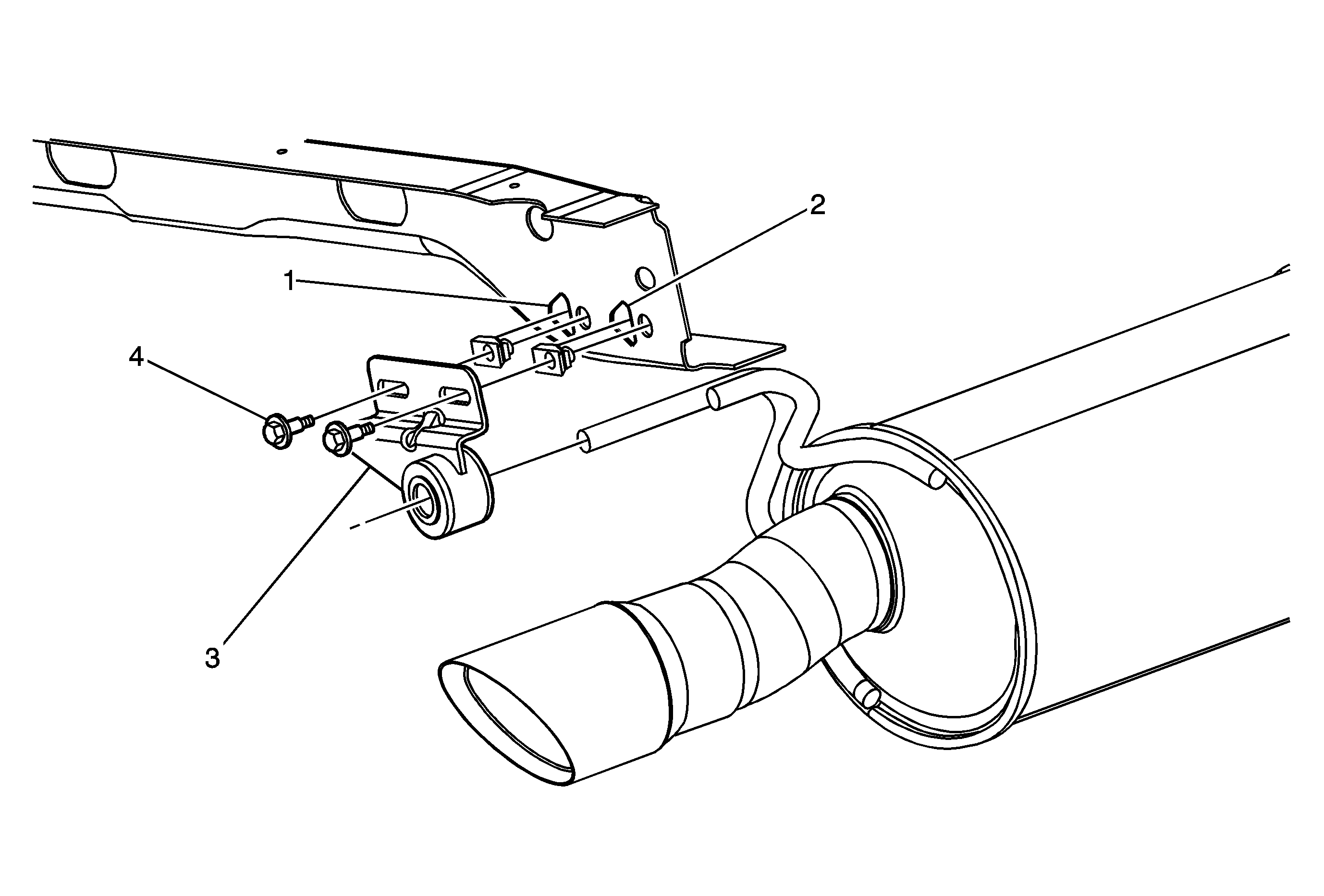
Adjustable Exhaust Hanger Bracket Installation

Important: This part includes two U-clips, two M8 x 13 bolts and one adjustable exhaust hanger bracket assembly.
- Install two U-clips in the slots (1 and 2) in the spare tire crossmember. Seat the clips into position.
- Install the adjustable exhaust hanger bracket assembly (3) onto the muffler hanger rod with the two M8 x 13 bolts (4) and hand tighten.
- Position the adjustable exhaust hanger bracket assembly (3) so that the exhaust tip is centered with 25 mm (+/- 5 mm) (1 in [+/- 0.20 in]) to the rear fascia opening. Tighten the M8 x 13 bolts (4).
Tighten
Tighten the bolts to 22 N·m (+/- 3 N·m) (16 lb ft [+/- 26 lb in).
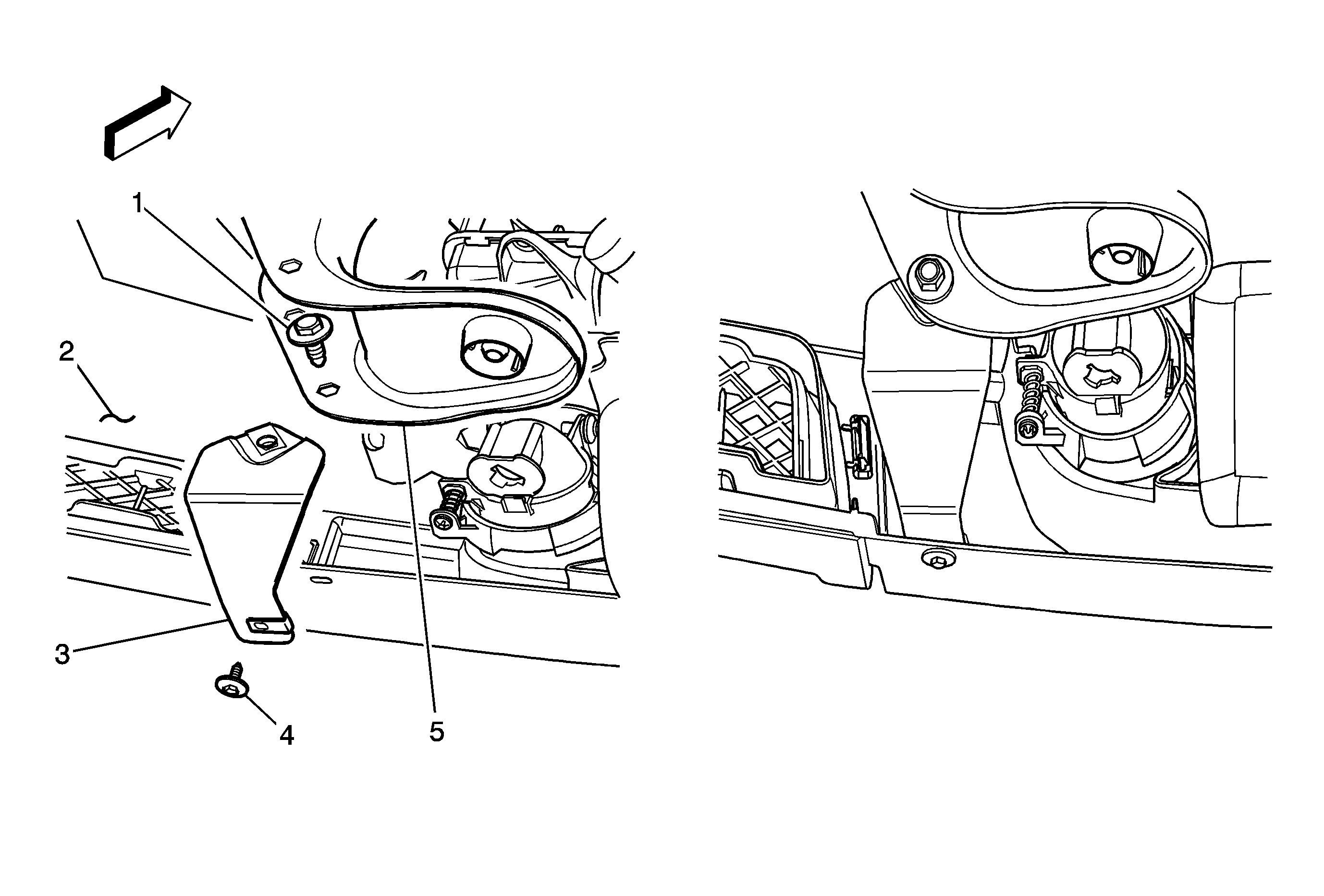
Front Fascia Lower Support Bracket Installation
Left Side of Vehicle Shown; Right Side Similar

Important: In the graphic above, the left side illustrates how the bracket should be installed while the right side shows how it should appear when installation is complete.
Important: The two front fascia brackets and four screws are included in the rear fascia lower kit.
- Place one of the front fascia brackets (3) between the radiator support bracket (5) and the front fascia (2).
- Install one M8 screw through the rear of the radiator support bracket (5) into the front fascia bracket (3).
- Install one M4.2 screw through the underneath of the front fascia (2) into the front fascia bracket (3).
- Repeat Steps 1-3 for the other side.
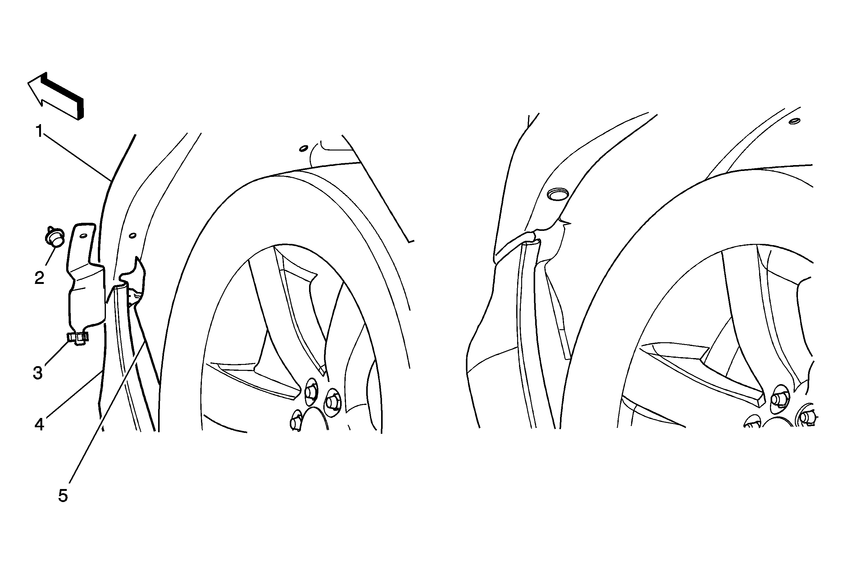
Front Wheel House Liner Cover Installation
Left Side of Vehicle Show, Right Side Similar

Important: In the graphic above, the left side illustrates how the cover should be installed while the right side shows how it should appear when installation is complete.
Important: This part includes one rear fascia lower, two push pins and two covers.
- Place a cover between the front wheel house liner (5) and the front fender/front fascia.
- Install a push pin (2) through the front fender (1) and cover.
- Install the clip (3) to the front wheel house liner (5).
- Repeat Steps 1-3 for the other side.
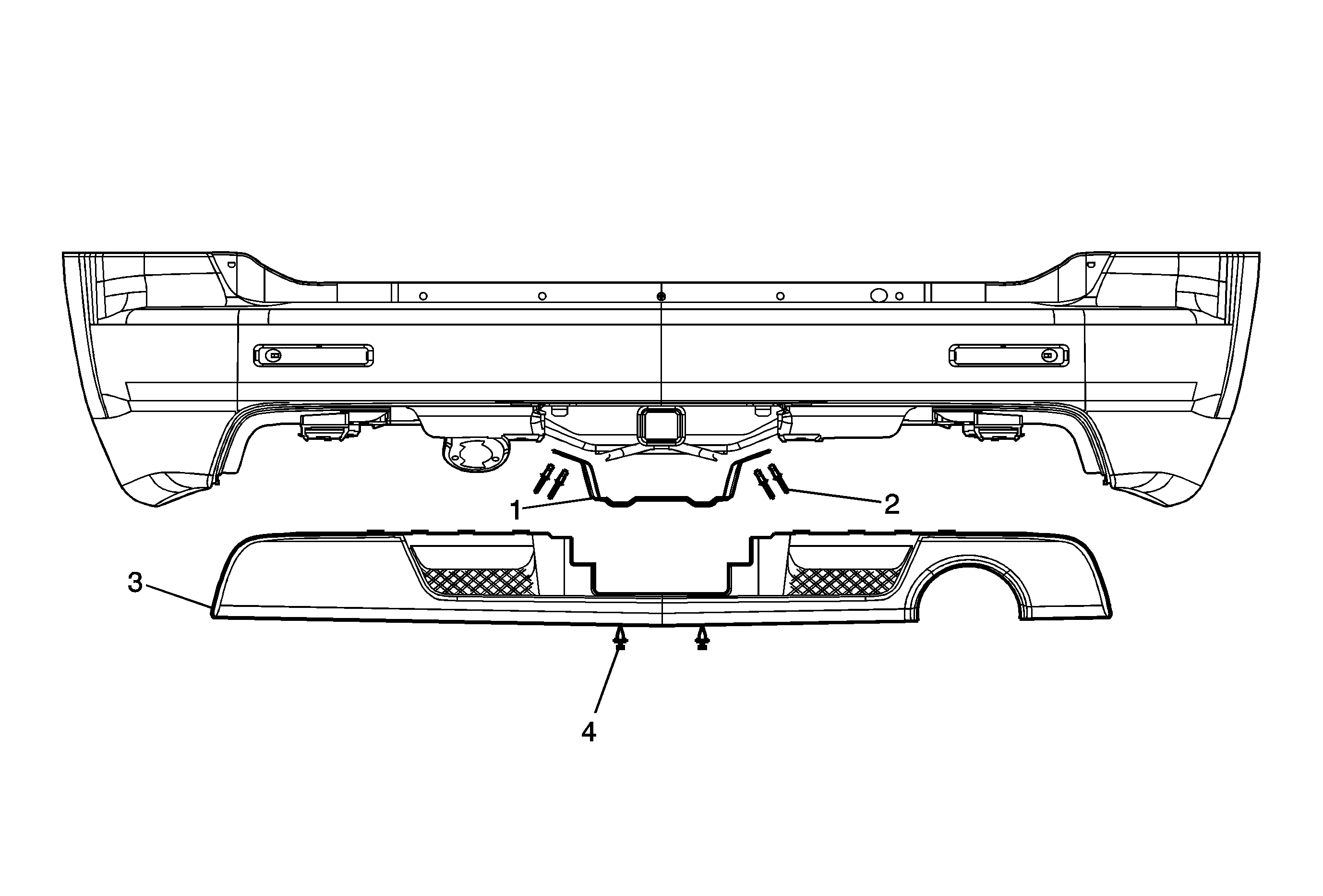
Rear Bumper Fascia Lower Installation

Important: This part includes two push pins, four rivets and one bracket.
- Position the rear fascia lower bracket (1) below the bumper so that the bracket angle is angled towards the front of the vehicle following the arrows marked on the part (1). Secure with the four rivets (2) to the rear bumper.
- Align "in vehicle position" the lower rear fascia assembly (3) to the slots in the upper rear fascia assembly. Press each snap into the corresponding slot, starting from the center and working outward one side at a time. Press firmly at each snap location to ensure proper engagement.
- Install the two push pins (4) to secure the rear fascia lower assembly (3) to the rear fascia lower bracket (1).
Tip
The snap tabs on the gray molded portion will make an audible snap when engaged; the painted portion will not. Perform the "push-pull" test to be sure each snap is secure. Do a visual inspection to make sure the entire
part is fully engaged at all locations.
