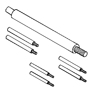
Accumulator Assembly, Spacer Plate, and Gaskets for Chevrolet TrailBlazer - 4WD 2004
Special Tools
| • | J 25025-B
Pump and Valve Body Alignment Pin Set |
Removal Procedure
- Raise and support the vehicle. Refer
to
Lifting and Jacking the Vehicle.
- Remove the transmission oil pan and filter. Refer to
Automatic Transmission Fluid and Filter Replacement.
Important: The 1-2 accumulator can be removed without removing the control valve assembly.
- Remove the control valve body. Refer to
Valve Body and Pressure Switch Replacement.
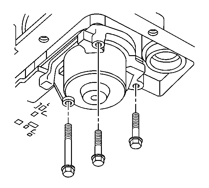
- Remove the accumulator cover retaining bolts.
- Remove the 1-2 accumulator cover assembly.
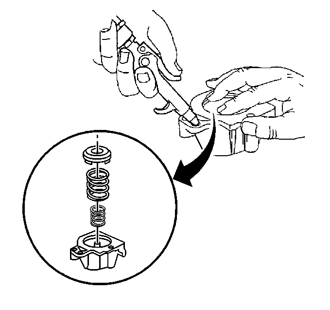
- Disassemble the 1-2 accumulator.
| 6.1. | Blow compressed air into the 1-2 accumulator cover, as shown, to remove the 1-2 accumulator piston. |
| 6.2. | Remove the 1-2 accumulator inner and outer springs. |
- Inspect the 1-2 accumulator inner and outer springs for cracks.
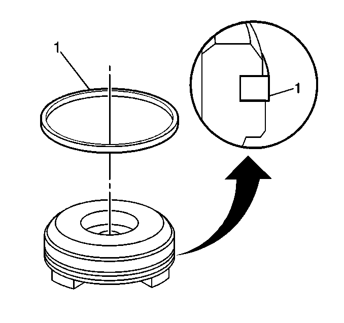
- Remove the 1-2 accumulator piston seal (1) from the 1-2 accumulator piston.
- Inspect the 1-2 accumulator piston for the following defects:
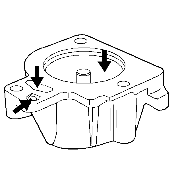
- Inspect the 1-2 accumulator cover for the following defects:
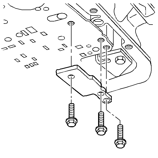
- Remove the spacer plate support retaining bolts.
Important: Use care not to drop the following items that will be removed along with the spacer plate:
| • | The 3-4 accumulator spring |
| • | The 3-4 accumulator pin |
- Remove the spacer plate support.
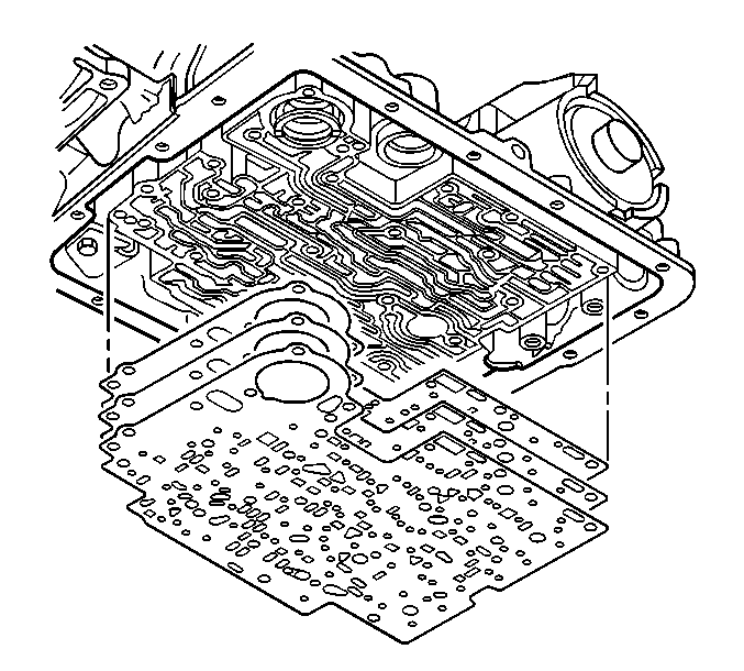
- Remove the spacer plate to valve body gasket, the spacer plate and the spacer
plate to transmission case gasket.
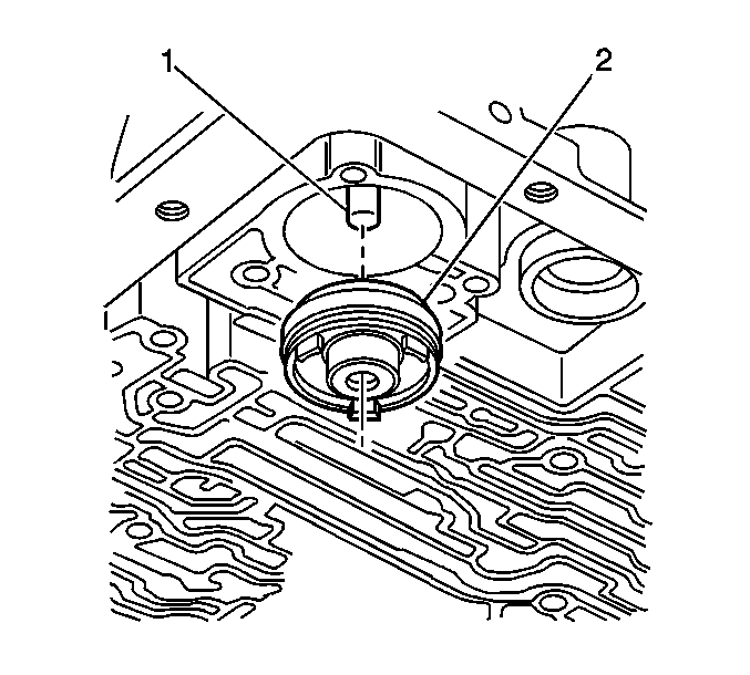
- Remove the 3-4 accumulator piston (2).
- Inspect the 3-4 accumulator spring for cracks.
- Remove the 3-4 accumulator piston seal (1) from the 3-4 accumulator piston.
- Inspect the 3-4 accumulator piston for the following defects:
Installation Procedure
- Install a new 3-4 accumulator piston seal (1) to the 3-4 accumulator piston.
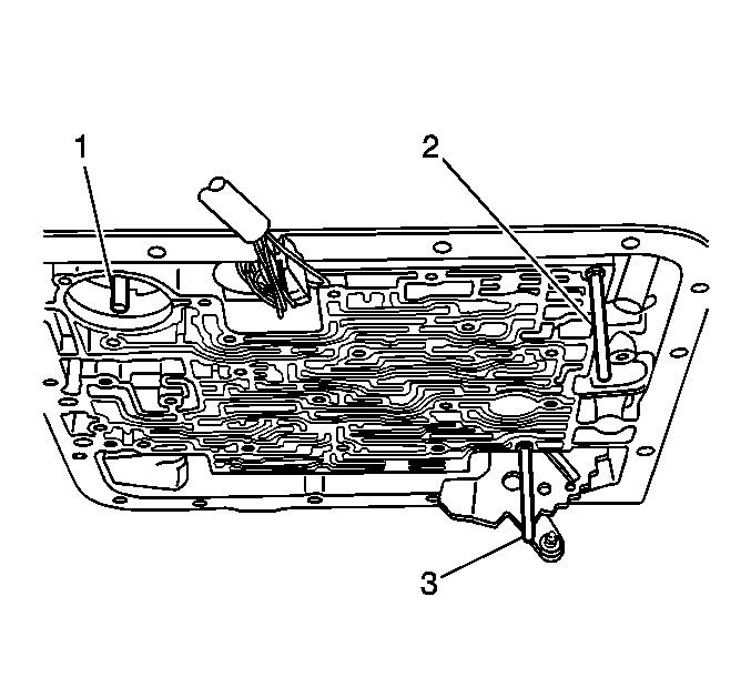
- Install the 3-4 accumulator pin (1) into the transmission case and retain the pin with
J 36850
.
- Install the 3-4 accumulator piston (2) onto the pin (1) in the transmission case.
Ensure that the 3-4 accumulator piston legs face away from the transmission case.
- Install the
J 25025-B
(2, 3) to the transmission case.
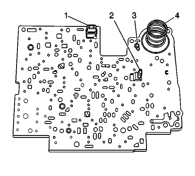
- Install the spacer plate to transmission case gasket and the spacer plate to valve body gasket to the spacer
plate. Use
J 36850
in order to retain the gaskets to the spacer plate.
| • | The case gasket is identified by a CA. |
| • | Be sure to place the case gasket on the transmission case side of the spacer plate. |
| • | The valve body gasket is identified by a VB. |
| • | Be sure to place the valve body gasket on the valve body side of the spacer plate. |
- Ensure that the solenoid screens (1, 2) are in place on the spacer plate.
- Place the checkball (3) on the spacer plate in the location shown.
- Place the 3-4 accumulator spring (4) on the spacer plate.
- Install the spacer plate and related components to the transmission.
Notice: Refer to Fastener Notice in the Preface section.
- Install the spacer plate support and the spacer plate support retaining bolts.
Tighten
Tighten the spacer plate support retaining bolts to 11 N·m (97 lb in).
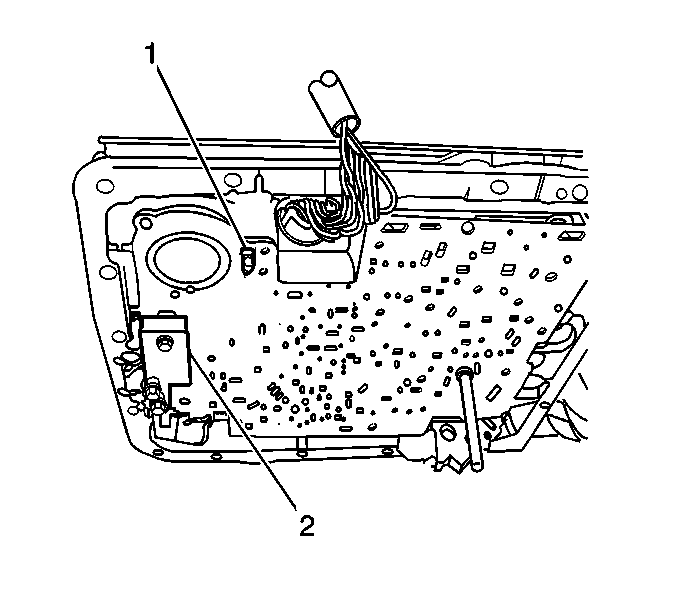
- After installing the spacer plate support (2), look through the hole in the spacer plate to ensure that
the checkball (1) has remained in the proper location.
- Install a new 1-2 accumulator piston seal (1) to the 1-2 accumulator piston.
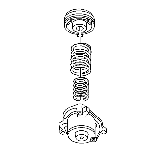
- Install the 1-2 accumulator inner and outer springs to the 1-2 accumulator cover.
- Install the 1-2 accumulator piston onto the pin in the 1-2 accumulator cover.
Ensure that the piston legs face the accumulator cover.
- Install the 1-2 accumulator
cover and the accumulator cover retaining bolts.
Tighten
Tighten the accumulator cover retaining bolts to 11 N·m (97 lb in).
- Remove the
J 25025-B
from the transmission case.
- Install the control valve body. Refer to
Valve Body and Pressure Switch Replacement.
- Install the transmission oil pan and filter. Refer to
Automatic Transmission Fluid and Filter Replacement.
- Lower the vehicle.
- Fill the transmission to the proper level with DEXRON® VI transmission fluid. Refer to
Transmission Fluid Check.
Important: It is recommended that transmission adaptive pressure (TAP) information be reset.
Resetting the TAP values using a scan tool will erase all learned values in all cells. As a result, the engine control module
(ECM), powertrain control module (PCM) or transmission control module (TCM) will need to relearn TAP values. Transmission performance may be affected as new TAP values are learned.
- Reset the TAP values. Refer to
Transmission Adaptive Functions.