Transmission Control Module Replacement LL8
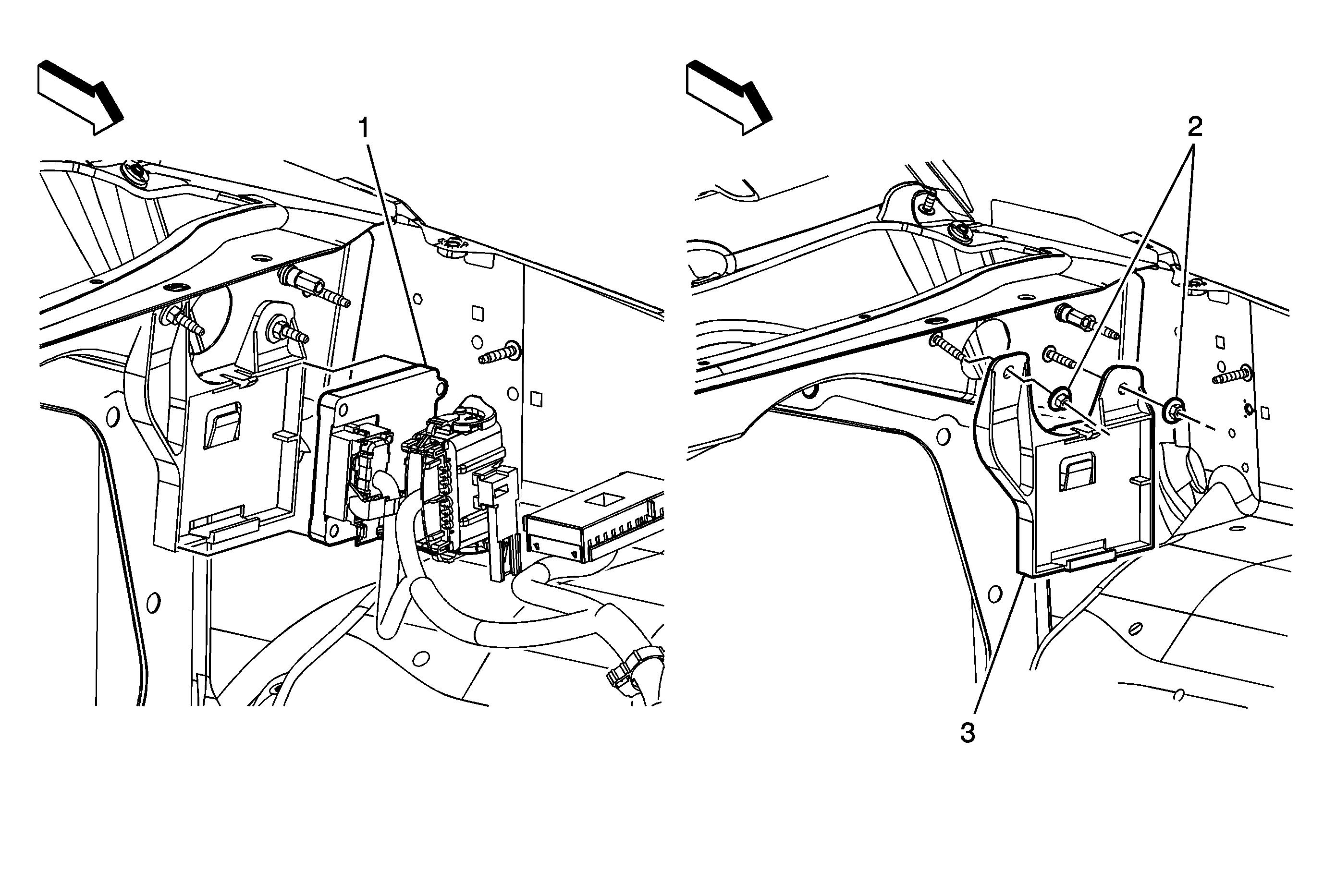
Callout | Component Name | ||||||
|---|---|---|---|---|---|---|---|
1 | Transmission Control Module (TCM) ProcedureA new TCM requires programming. Refer to Control Module References . Tip
| ||||||
2 | TCM Bracket Nut (Qty: 2) Notice: Refer to Fastener Notice in the Preface section. Tighten: | ||||||
3 | TCM Bracket |
Transmission Control Module Replacement LH6
Service of the transmission control module (TCM) should consist of reprogramming of the TCM. If the diagnostic procedures call for the TCM to be replaced, the replacement TCM should be checked to ensure that the correct part is being used. If the correct part is being used, remove the faulty TCM and install the new service TCM. The replacement TCM must be programmed.
Removal Procedure
- Disconnect the negative battery cable. Refer to Battery Negative Cable Disconnection and Connection.
- Disconnect the cooling fan electrical connector for additional clearance while removing the TCM.
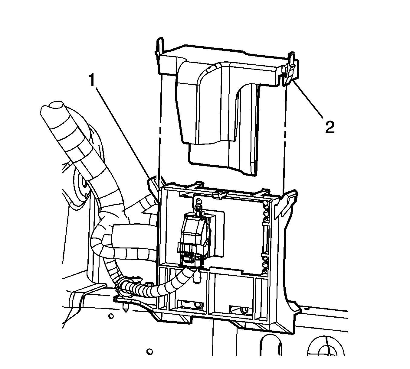
- Depress the engine control module (ECM)/TCM cover retainers (2).
- Remove the ECM/TCM cover from the ECM/TCM bracket (1).
- Disconnect the TCM electrical connector (1) from the TCM (2)
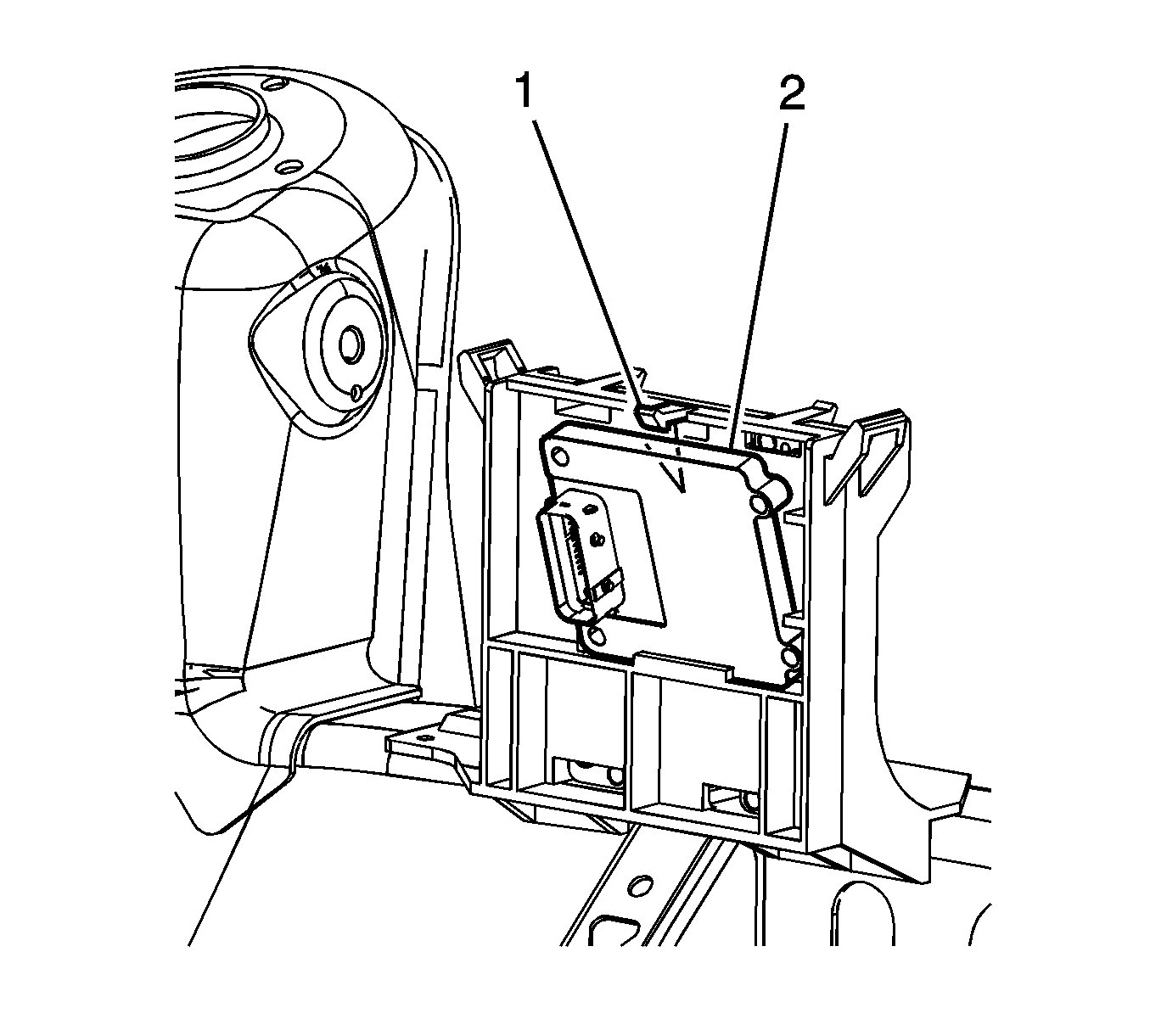
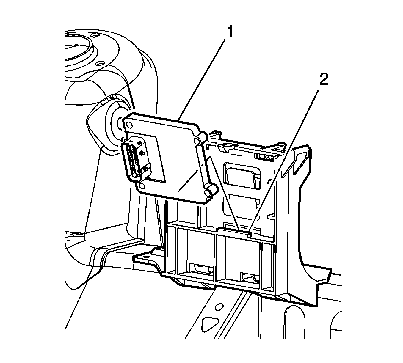
- Release the bracket TCM retainer (1).
- Tilt the TCM (2) away from the ECM/TCM bracket.
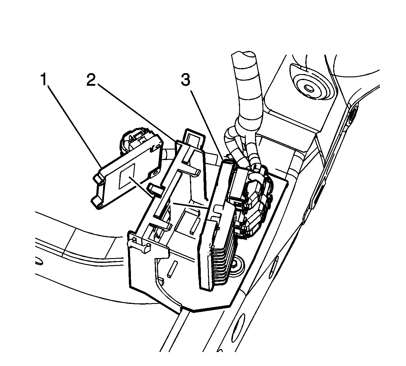
- Remove the TCM (1) from the TCM bracket (2).
- Only when replacement of the ECM/TCM bracket (2) is necessary, remove the ECM (3). Refer to Engine Control Module Replacement.
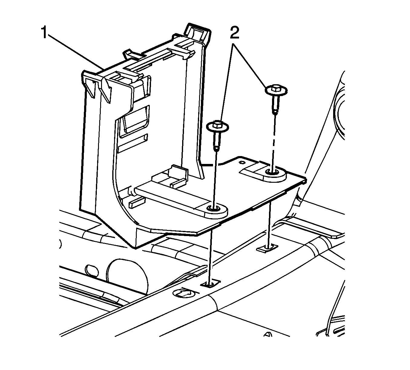
- Remove the ECM/TCM bracket retaining bolts (2).
- Remove the ECM/TCM bracket (1) from the vehicle frame.
Notice: Refer to Handling Electrostatic Discharge Sensitive Parts Notice in the Preface section.
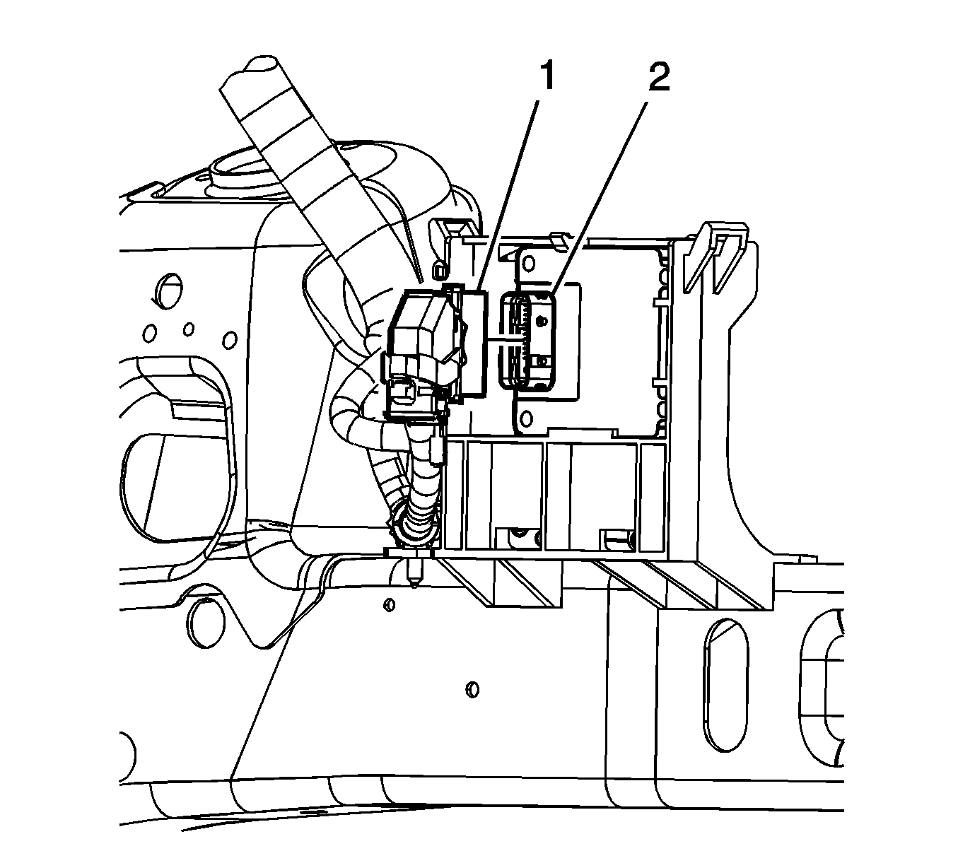
Important: It is not necessary to disconnect the TCM electrical connectors in order to remove the TCM from the ECM/TCM bracket. Only disconnect the electrical connectors if servicing of component requires disconnecting of the electrical connectors.
Important: Remove any debris from around the TCM connector surfaces before servicing the TCM. Inspect the TCM module connector gaskets when diagnosing or replacing the TCM. Ensure that the gaskets are installed correctly. The gaskets prevent contaminant intrusion into the TCM.
Installation Procedure
- If the ECM/TCM bracket (1) was previously removed, install the ECM/TCM bracket (1) to the vehicle frame.
- Install the ECM/TCM bracket retaining bolts (2).
- Tighten the ECM/TCM bracket bolts.
- If the ECM was previously removed from the ECM/TCM bracket (2), install the ECM (3). Refer to Engine Control Module Replacement.
- Insert the TCM (1) into the retaining slot of the ECM/TCM bracket (2).
- Secure the TCM (2) to the ECM/TCM mounting bracket ensuring the TCM retaining tab (1) is fully engaged.
- Connect the ECM electrical connector (1) to the TCM (2) if previously removed.
- Install the ECM/TCM cover (2) to the ECM/TCM bracket (1).
- Ensure the ECM/TCM cover retainers (2) are fully engaged with the ECM/TCM bracket (1).
- Connect the cooling fan electrical connector.
- Connect the negative battery cable. Refer to Battery Negative Cable Disconnection and Connection.
- If the TCM was replaced the replacement TCM must be programmed. Refer to Control Module References .

Notice: Refer to Fastener Notice in the Preface section.
Tighten
Tighten the bolts to 10 N·m (89 lb in).


