For 1990-2009 cars only
Cylinder Head Replacement - Right Side 5.3L
Special Tools
J 45059 Angle Meter
Removal Procedure
- Remove the intake manifold. Refer to Intake Manifold Replacement.
- Remove the oil level indicator. Refer to Oil Level Indicator and Tube Replacement.
- Remove the coolant air bleed pipe. Refer to Coolant Air Bleed Pipe Assembly Replacement.
- Remove the right exhaust manifold. Refer to Exhaust Manifold Replacement - Right Side.
- Remove the pushrods. Refer to Valve Rocker Arm and Push Rod Replacement.
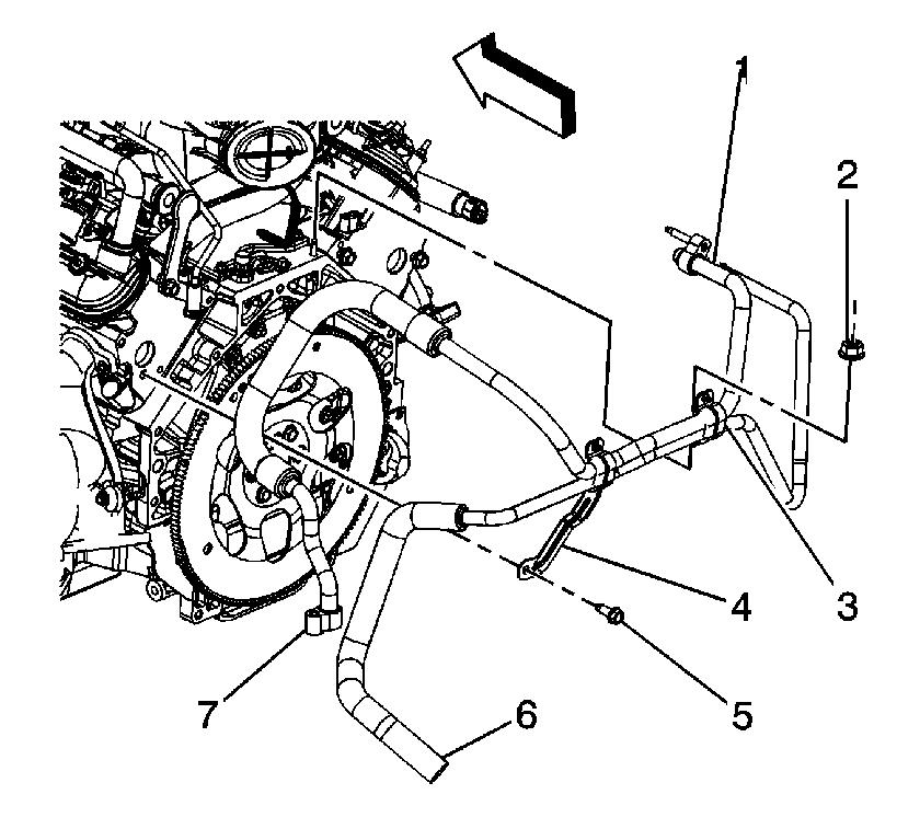
- If equipped, remove the auxiliary air conditioning (A/C) bracket nut (2).
- Remove the cylinder head. Refer to Cylinder Head Removal - Right Side.
- Clean and inspect the cylinder head. Refer to Cylinder Head Cleaning and Inspection.

Installation Procedure
- Install the cylinder head. Refer to Cylinder Head Installation - Right Side.
- If equipped, install the auxiliary A/C bracket nut (2) and tighten to 20 N·m (15 lb ft).
- Install the pushrods. Refer to Valve Rocker Arm and Push Rod Replacement.
- Install the intake manifold. Refer to Intake Manifold Replacement.
- Install the right exhaust manifold. Refer to Exhaust Manifold Replacement - Right Side.
- Install the coolant air bleed pipe. Refer to Coolant Air Bleed Pipe Assembly Replacement.
- Install the oil level indicator. Refer to Oil Level Indicator and Tube Replacement.
Caution: Refer to Fastener Caution in the Preface section.

Cylinder Head Replacement - Right Side 6.0L
Removal Procedure
- Remove the oil level indicator. Refer to Oil Level Indicator and Tube Replacement.
- Remove the coolant air bleed pipe. Refer to Coolant Air Bleed Pipe Assembly Replacement.
- Remove the right exhaust manifold. Refer to Exhaust Manifold Replacement - Right Side.
- Remove the pushrods. Refer to Valve Rocker Arm and Push Rod Replacement.
- If equipped, remove the auxiliary air conditioning (A/C) bracket nut (2).
- Remove the cylinder head. Refer to Cylinder Head Removal - Right Side.
- Clean and inspect the cylinder head. Refer to Cylinder Head Cleaning and Inspection.

Installation Procedure
- Install the cylinder head. Refer to Cylinder Head Installation - Right Side.
- If equipped, install the auxiliary air conditioning (A/C) bracket nut (2).
- Install the pushrods. Refer to Valve Rocker Arm and Push Rod Replacement.
- Install the right exhaust manifold. Refer to Exhaust Manifold Replacement - Right Side.
- Install the coolant air bleed pipe. Refer to Coolant Air Bleed Pipe Assembly Replacement.
- Install the oil level indicator. Refer to Oil Level Indicator and Tube Replacement.
Caution: Refer to Fastener Caution in the Preface section.

Tighten
Tighten the nut to 20 N·m (15 lb ft).
