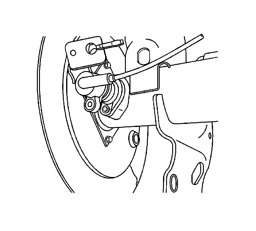
For 1990-2009 cars only
Removal Procedure
- Raise and support the vehicle. Refer to Lifting and Jacking the Vehicle.
- Disconnect the wheel speed sensor electrical connector.
- Remove the wheel speed sensor bolt.
- Remove the wheel speed sensor.

Installation Procedure
- Ensure the sensor and sensor boss (face and inner diameter) are clean and free of any debris and/or metal chips.
- Place a small amount of axle lube inside the sensor boss inner diameter to ensure the seal is properly lubricated and does not roll over when installed.
- Insert the wheel speed sensor into the hole using equal pressure to seat the sensor squarely on the sensor boss face.
- Align the sensor with the bolt hole and install the wheel speed sensor bolt and tighten to 18 N·m (13 lb ft).
- Connect the wheel speed sensor electrical connector.
- Lower the vehicle.
- Perform a low speed test to ensure the wheel speed sensor is functioning properly:

Caution: Refer to Fastener Caution in the Preface section.
| 7.1. | Start the engine and allow it to idle. |
| 7.2. | Verify the ABS indicator or the traction assist indicator remains illuminated. |
| 7.3. | If the ABS indicator or the traction assist indicator remains illuminated, DO NOT proceed to drive the vehicle until it is diagnosed and repaired. Check the wheel speed sensor electrical connector to ensure it is not damaged and is installed properly. If the lamp remains illuminated, refer to Symptoms - Antilock Brake System. |
| 7.4. | Select a smooth, dry, clean, and level road or large lot that is as free of traffic and obstacles as possible. |
| 7.5. | Drive the vehicle and maintain a speed of at least 16 km/h (10 mph) for at least 5 seconds. |
| 7.6. | Stop the vehicle and check to see if the ABS indicator or the traction assist indicator is illuminated. |
| 7.7. | If an indicator is illuminated, refer to Diagnostic Starting Point - Antilock Brake System. |
