For 1990-2009 cars only
Removal Procedure
- Raise the vehicle. Refer to Lifting and Jacking the Vehicle.
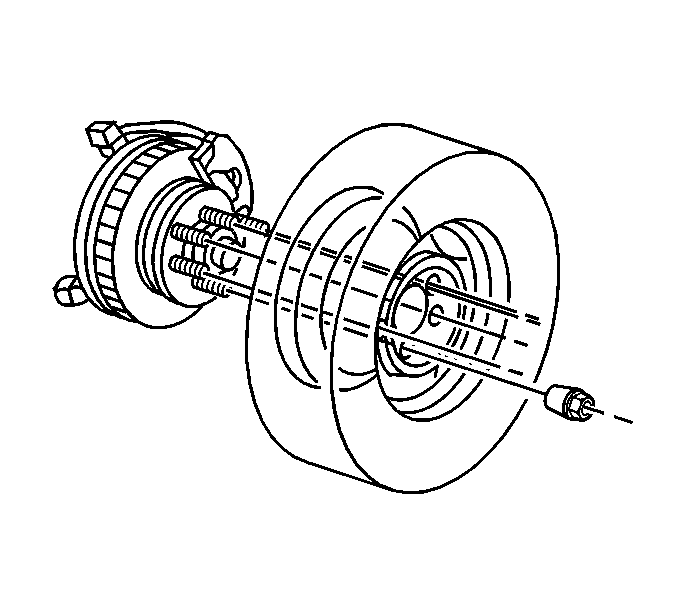
- Remove the tire and wheel assembly. Refer to Tire and Wheel Removal and Installation.
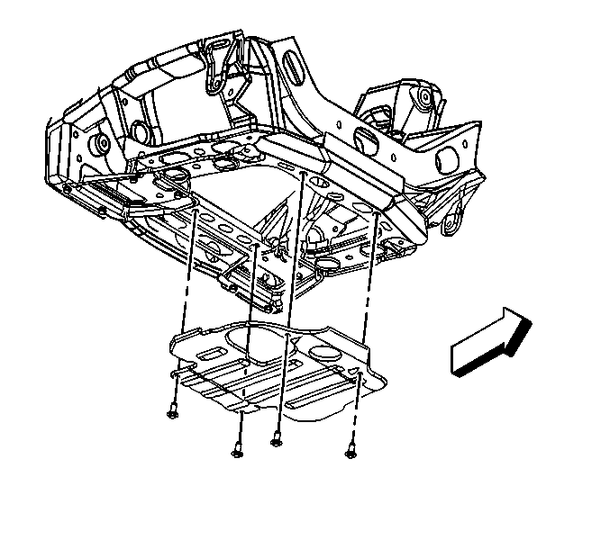
- Remove the engine protection shield. Refer to Engine Protection Shield Replacement.
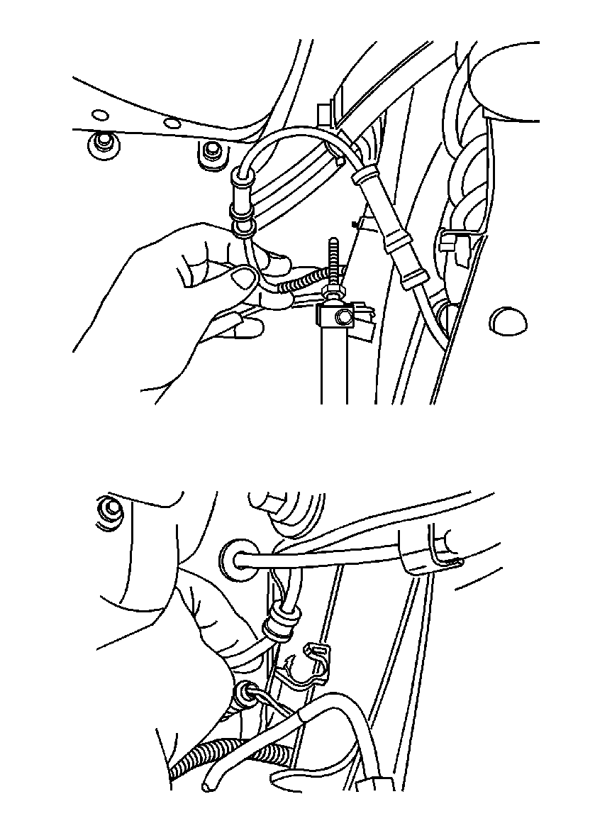
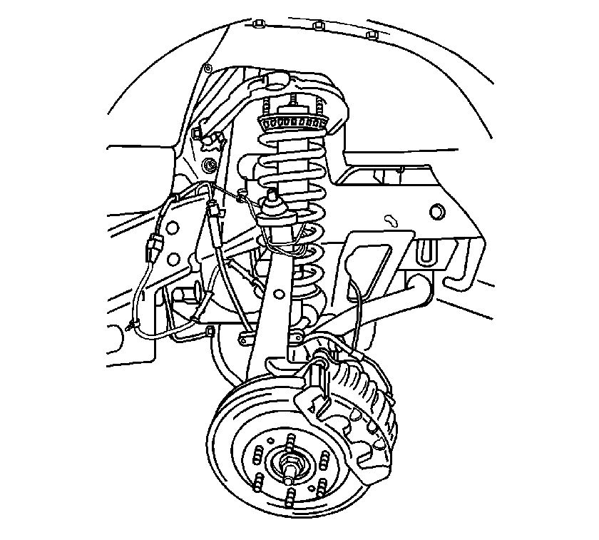
- Remove the wheel speed sensor wiring harness from the retainers.
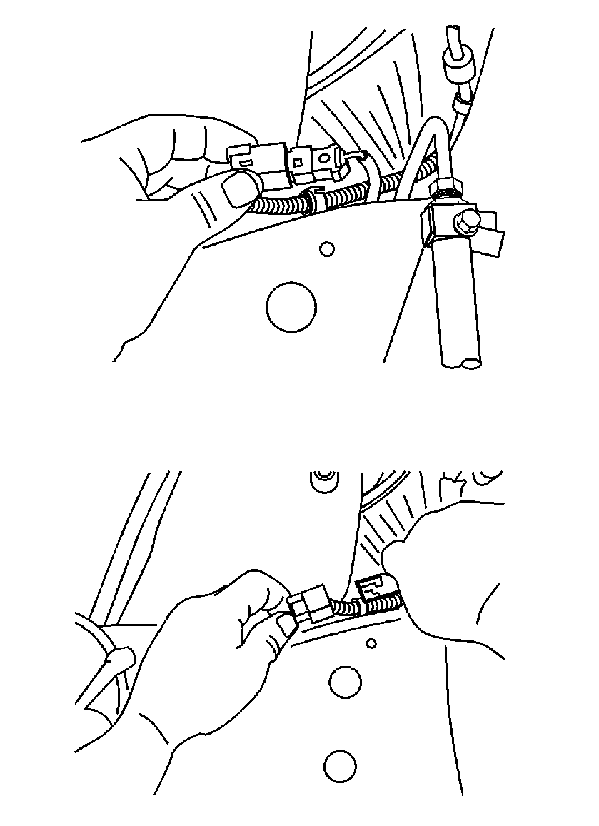
- Disconnect the wheel speed sensor from the harness.
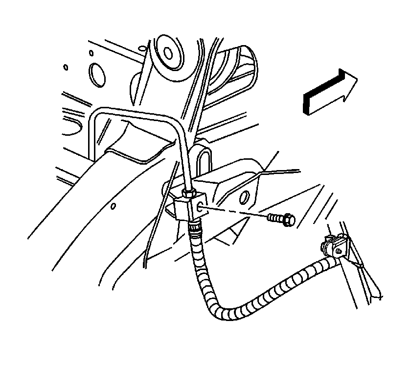
- Remove the retaining bolt for the front brake hose.
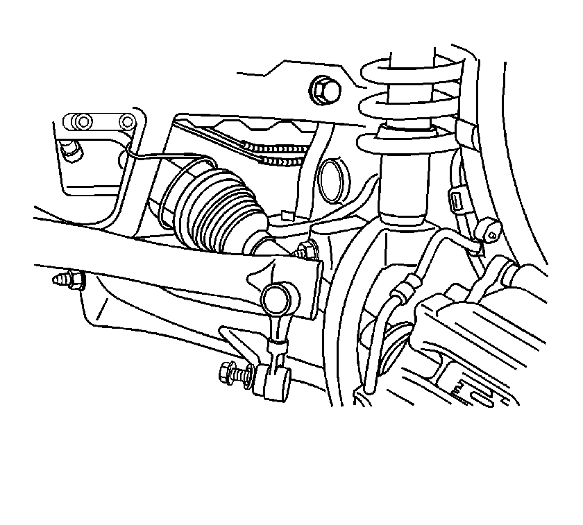
- Remove the front stabilizer bar link from the lower control arm. Refer to Stabilizer Shaft Link Replacement.
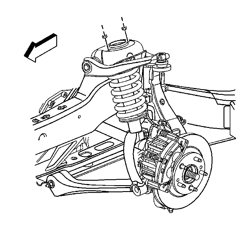
- Remove the upper shock module retaining from the shock tower.
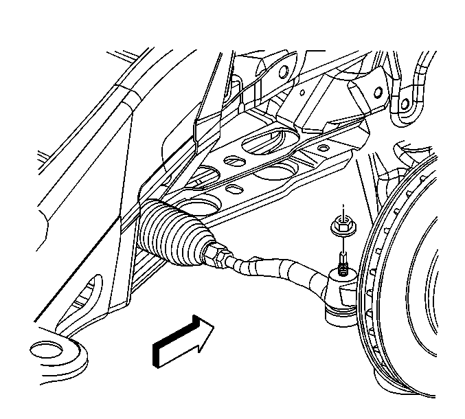
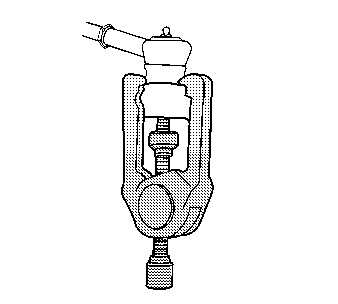
- Remove the tie rod end from the steering knuckle. Refer to Steering Linkage Outer Tie Rod Replacement.
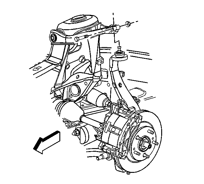
- Remove the left and right upper ball joint pinch bolt and nut.
- Remove the shock module from the shock tower.
- Remove the steering knuckle from the upper control arm.
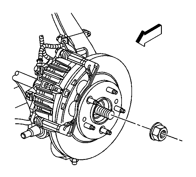
- Remove the front wheel drive axle from the steering knuckle.
- Using mechanics wire or hook, support the front shock module/steering knuckle to the frame.
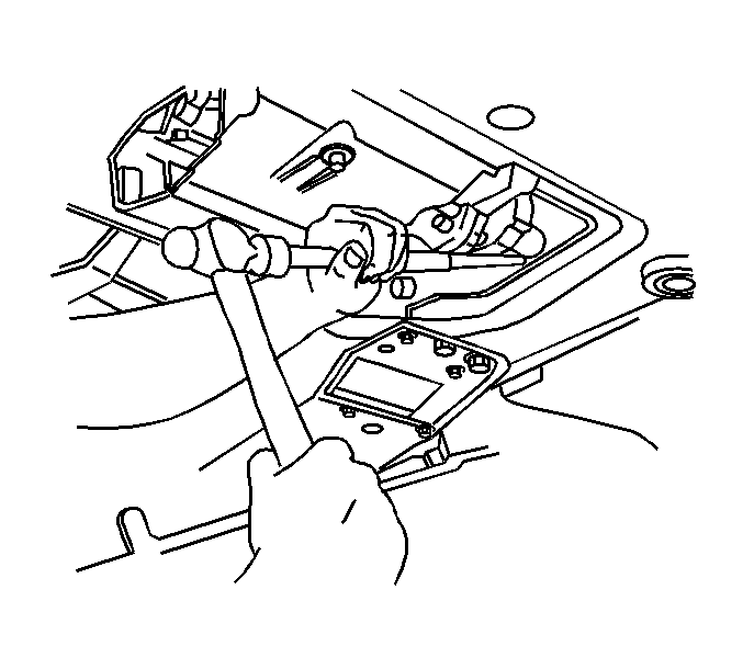
- Disconnect the left side wheel drive shaft from the differential carrier assembly by placing a brass drift against the tripot housing. Firmly strike the brass drift outward from the case with a hammer. Strike hard enough to overcome the snap ring pressure holding in the shaft.
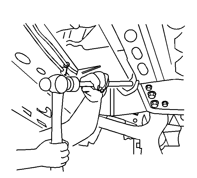
- Disconnect the right side wheel drive shaft from the clutch fork housing assembly by placing a brass drift against the tripot housing. Firmly strike the brass drift outward from the case with a hammer. Strike hard enough to overcome the snap ring pressure holding in the shaft.
- Pull the wheel drive shaft straight out from the differential carrier assembly or the clutch fork housing assembly.
- Remove the wheel drive shaft.
Installation Procedure
- Install the front wheel drive axle front differential assembly.
- Remove the mechanics wire or hook from the front shock module/steering
- Install the front wheel drive axle in the steering knuckle.
- Position the shock module in the shock tower.
- Install the shock module into the shock tower
- Install the upper ball joint in the upper control arm.
- Install the pinch bolt and nut. For the proper torque specification, refer to Steering Knuckle Replacement.
- Install the shock module retaining nuts. For the proper torque specification, refer to Shock Absorber and Spring Assembly Replacement.
- Install the front wheel drive shaft retaining.
- Install the new front wheel drive shaft retaining nut and tighten to 140 N·m (103 lb ft).
- Install the tie rod end in the steering knuckle. Refer to Steering Linkage Outer Tie Rod Replacement.
- Install the stabilizer bar link. Refer to Stabilizer Shaft Link Replacement.
- Install the front brake hose retaining bolt. Refer to Front Brake Hose Replacement.
- Install the front wheel speed sensor wiring harness in the retainers.
- Reconnect the front wheel speed sensors electrical connector.
- Install the engine protection shield. Refer to Engine Protection Shield Replacement.
- Install the tire and wheel assembly. Refer to Tire and Wheel Removal and Installation.
- Lower the vehicle. Refer to Lifting and Jacking the Vehicle.


Caution: Refer to Fastener Caution in the Preface section.
