For 1990-2009 cars only
Navigation Control Processor Bracket Replacement Envoy XL
Removal Procedure
- Fold and tumble the right rear seat to a cargo position.
- Leaving the electrical connectors attached, remove the communication interface module from the vehicle communication interface module (VCIM) bracket. Refer to Communication Interface Module Replacement.
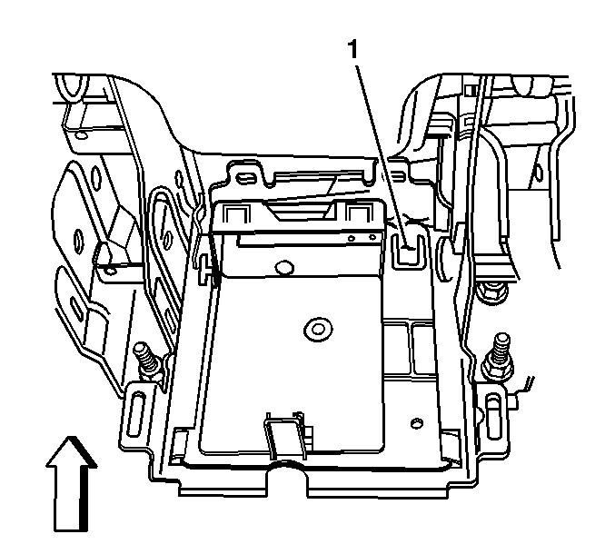
- Using a flat bladed tool, release the retaining tab (1) on the VCIM bracket.
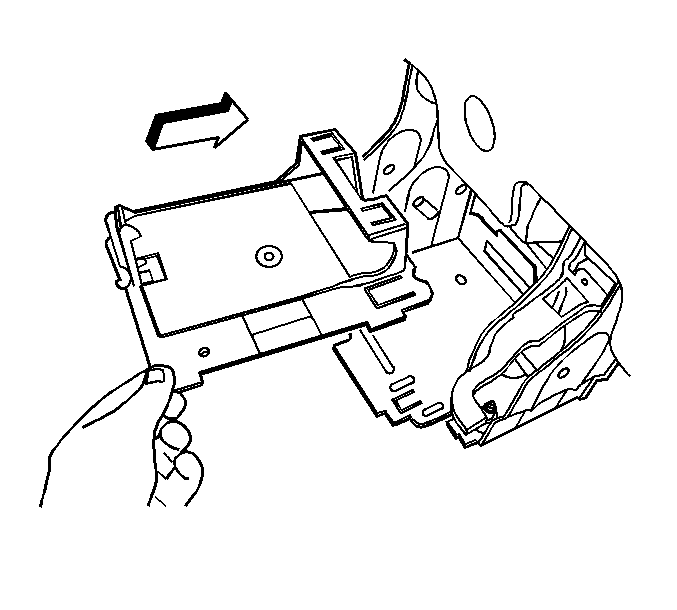
- Slide the VCIM bracket rearward until the retaining tabs are released from the seat bracket.
- Remove the VCIM bracket from vehicle.
- Slide the VCIM bracket rearward until the retaining tabs are released from the seat bracket.
- Remove the VCIM bracket from vehicle.


Installation Procedure
- Position the VCIM bracket to the seat bracket.
- Slide the VCIM bracket forward until the retaining tabs become locked to the seat bracket.
- Ensure the retaining tab (1) on the VCIM bracket is properly seated.
- Install the communication interface module. Refer to Communication Interface Module Replacement.
- Position the right second row seat to a passenger position.


Navigation Control Processor Bracket Replacement Envoy, TrailBlazer
Removal Procedure
- Remove the right rear seat cushion. Refer to Rear Seat Cushion Replacement.
- Remove the communication interface module. Refer to Communication Interface Module Replacement.
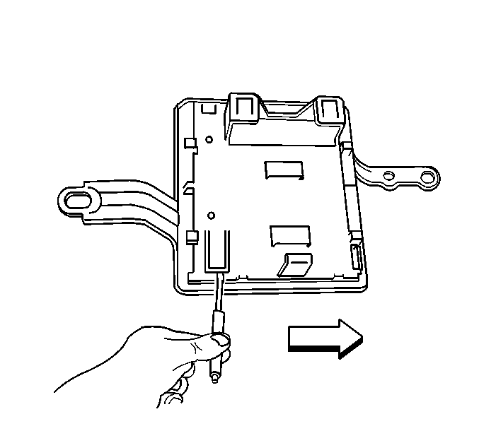
- Using a flat-bladed tool, release the retaining tab on the upper bracket.
- Slide the upper bracket inboard until the retaining tabs are released from the processor bracket.
- Remove the upper bracket from the processor bracket.
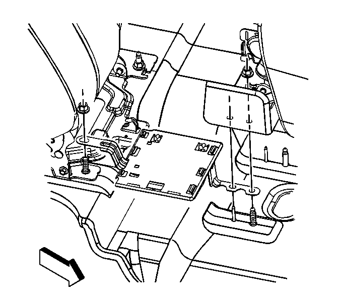
- Remove the nut that retains the processor bracket to the rear seat back stud.
- Remove the processor bracket from the vehicle.


Installation Procedure
- Install the processor bracket to the rear seat studs.
- Install the nut to the rear seat back stud.
- Position the upper bracket to the processor bracket.
- Slide the upper bracket outboard until all the retaining tabs are seated to the processor bracket.
- Install the communication interface module. Refer to Communication Interface Module Replacement.
- Install the right rear seat cushion. Refer to Rear Seat Cushion Replacement.

Caution: Refer to Fastener Caution in the Preface section.
Tighten
Tighten the nut to 45 N·m (33 lb ft).

