For 1990-2009 cars only
Removal Procedure
- Remove the lower control arm assembly. Refer to Lower Control Arm Replacement.
- Install the lower control arm in a vise.
- Drill or grind off the head of the rivet.
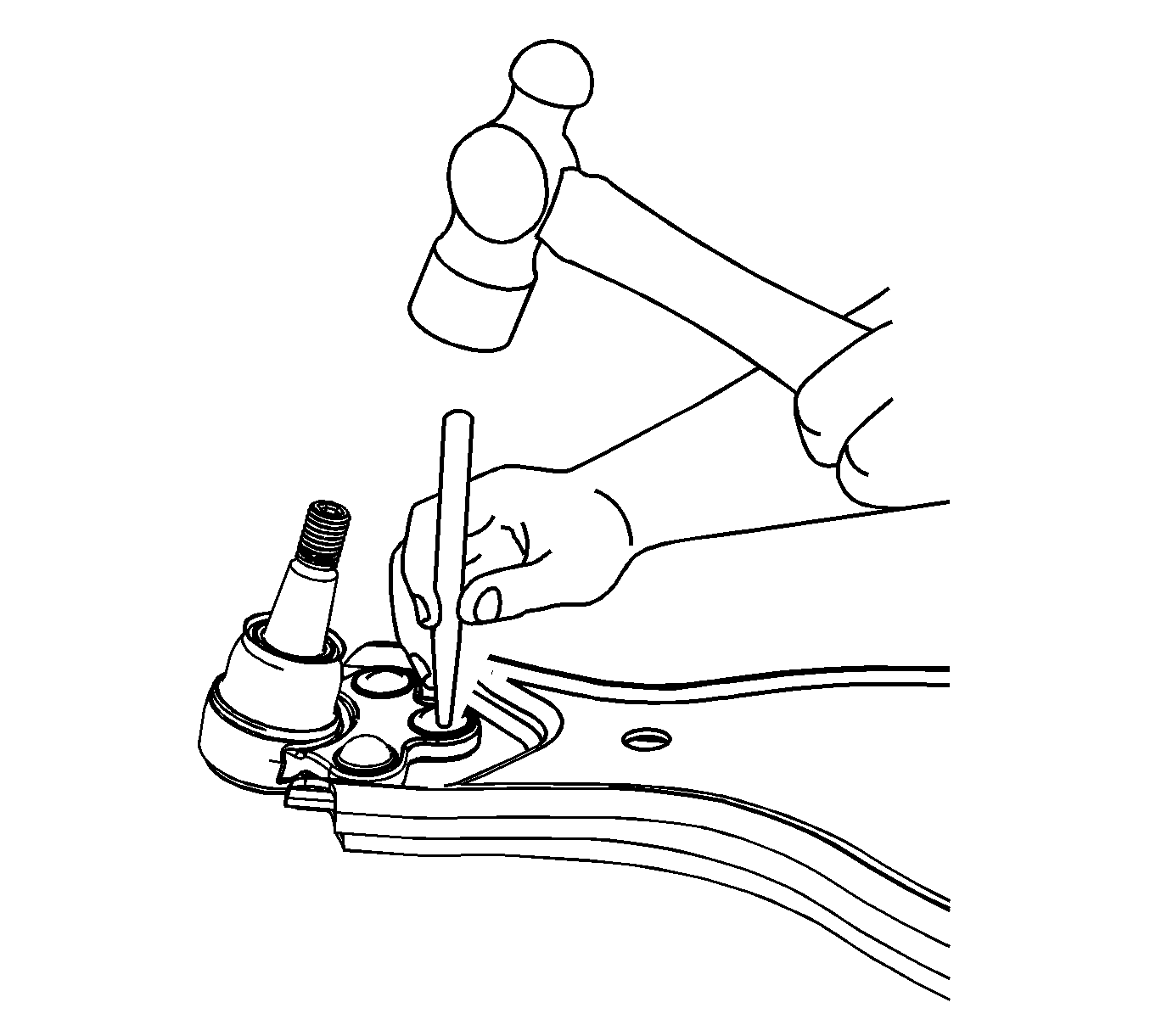
- Use a punch and a hammer to loosen the rivets from the lower control arm.
- Remove the rivets from the lower control arm.
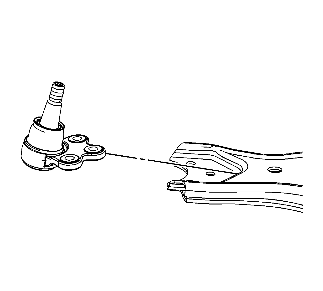
- Remove the ball joint from the lower control arm.
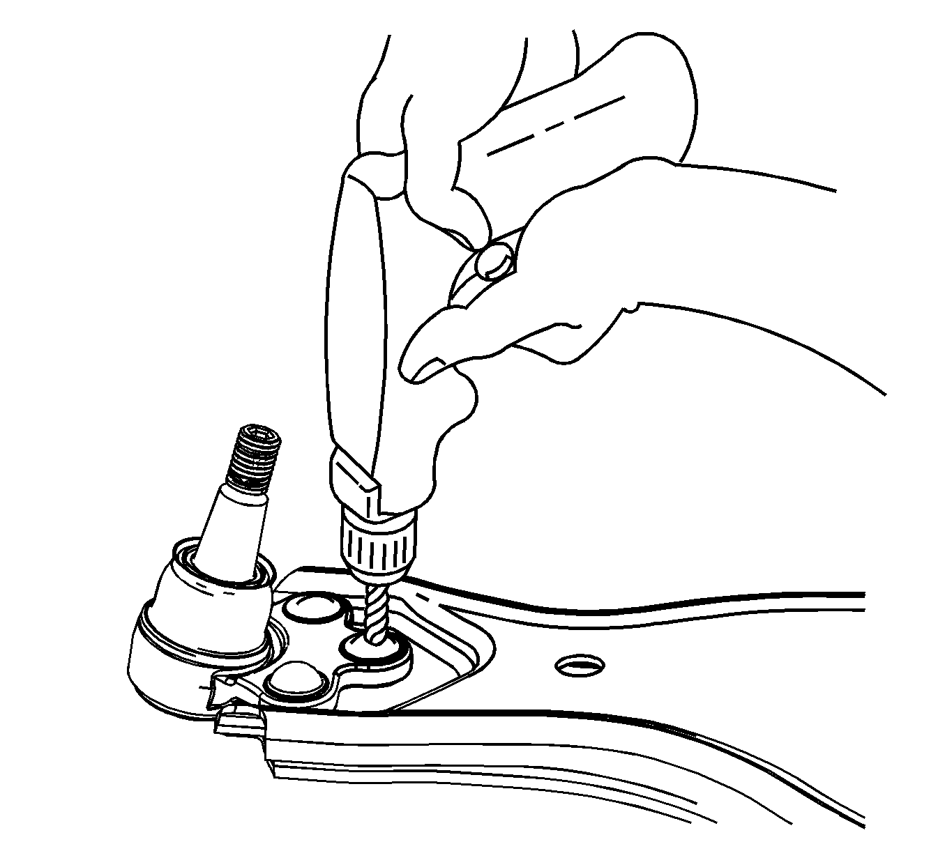
Note: Use a center punch to aid in starting the drill if drilling the rivet.
Installation Procedure
- Position the ball joint on the lower control arm.
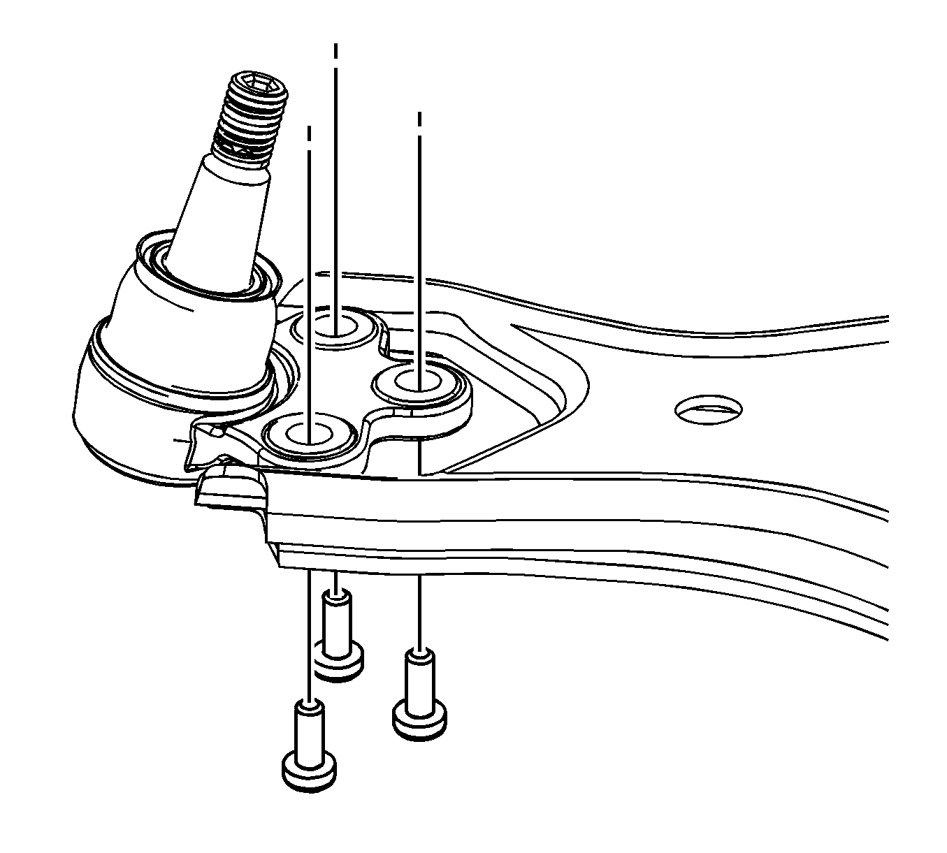
- Install the ball joint mounting nuts and bolts.
- Remove the lower control arm assembly from the vise.
- Install the lower control arm. Refer to Lower Control Arm Replacement.
- Check the front end alignment of the vehicle. Refer to Wheel Alignment Specifications.

Caution: Refer to Fastener Caution in the Preface section.
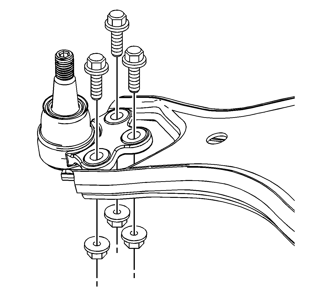
Note: When tightening the mounting nuts and bolts for the ball joint, hold the bolt and torque the nut for the proper torque measure.
Tighten
Tighten the mounting nuts to 68 N·m (50 lb ft).
