For 1990-2009 cars only
Removal Procedure
- Raise and support the vehicle. Refer to Lifting and Jacking the Vehicle.
- Remove the front tires and wheels. Refer to Tire and Wheel Removal and Installation.
- Remove the bolt from the intermediate shaft bracket to the front cradle. Refer to Intermediate Drive Shaft Replacement.
- Remove the rear propeller shaft, if equipped. Refer to Propeller Shaft Replacement.
- Remove the outer tie rod ends from the steering knuckle. Refer to Steering Linkage Outer Tie Rod Replacement.
- Remove the stabilizer shaft links at the stabilizer bar. Refer to Stabilizer Shaft Link Replacement.
- Position adjustable jack stand underneath the left and right side at the rear of the front cradle.
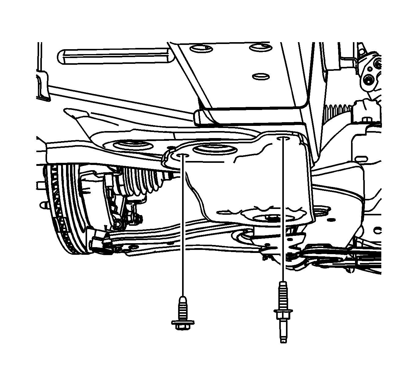
- Remove the left and right frame reinforcement mounting bolts. Left side shown, right side similar.
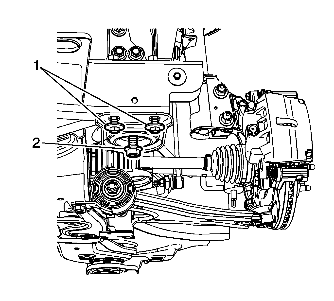
- Loosen the front frame reinforcement mounting bolts (1). Left side shown, right side similar.
- Loosen the front frame mounting bolts (2). Left side shown, right side similar.
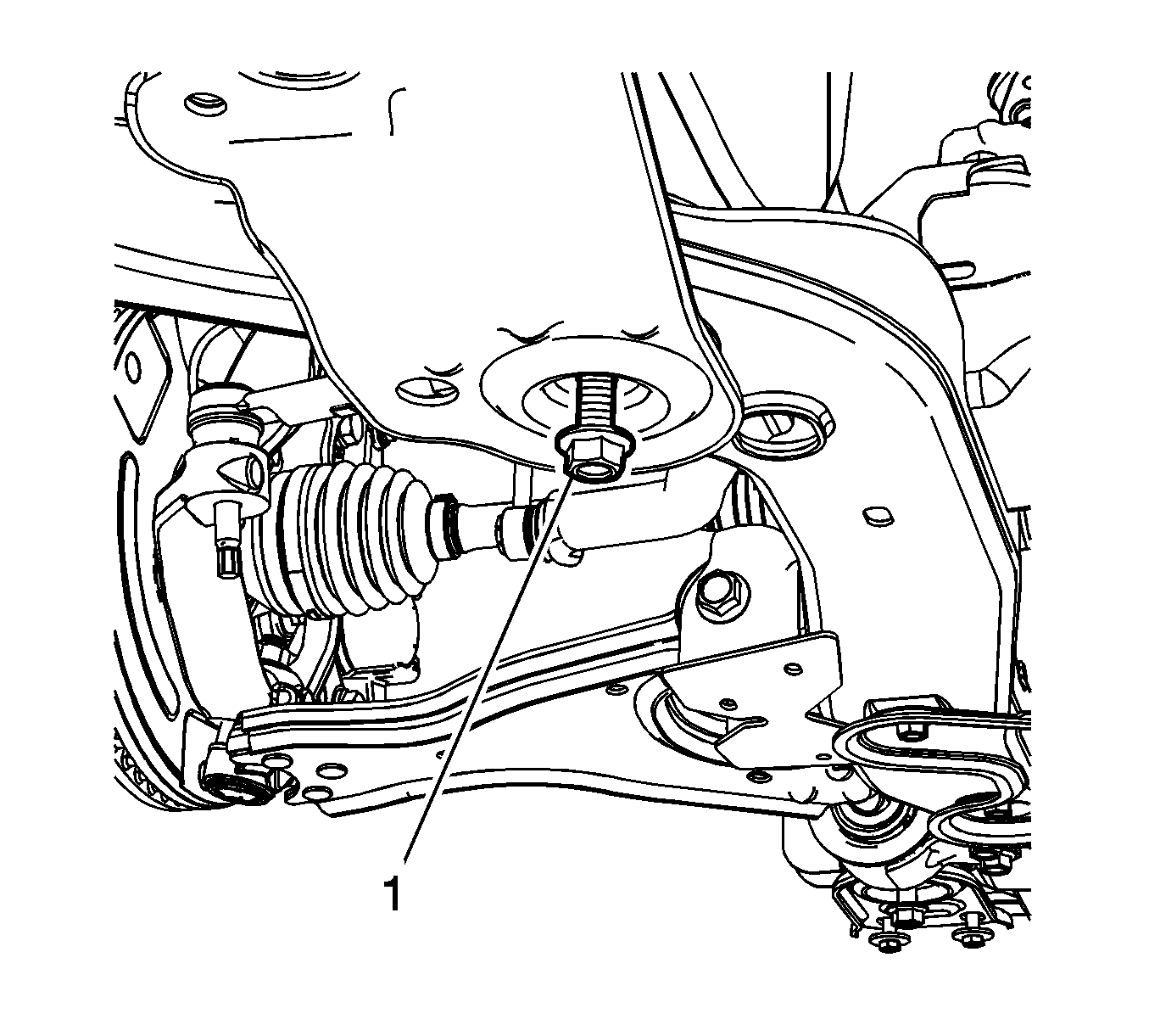
- Loosen the rear frame mounting bolts (1).
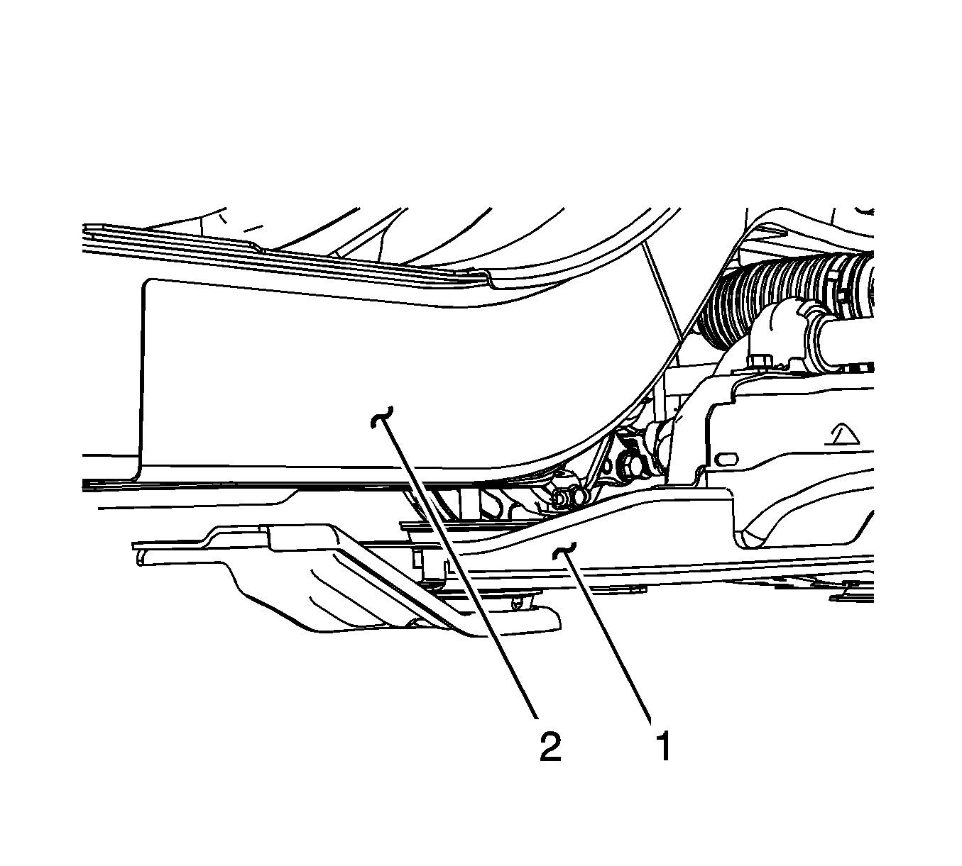
- Lower the frame (1) from the frame rail (2) until enough clearance is gained to remove the stabilizer shaft.
- Remove both left and right stabilizer shaft insulators. Refer to Stabilizer Shaft Insulator Replacement.
- Remove the stabilizer shaft from the vehicle.
Note: If replacing the stabilizer shaft, use NEW insulators.
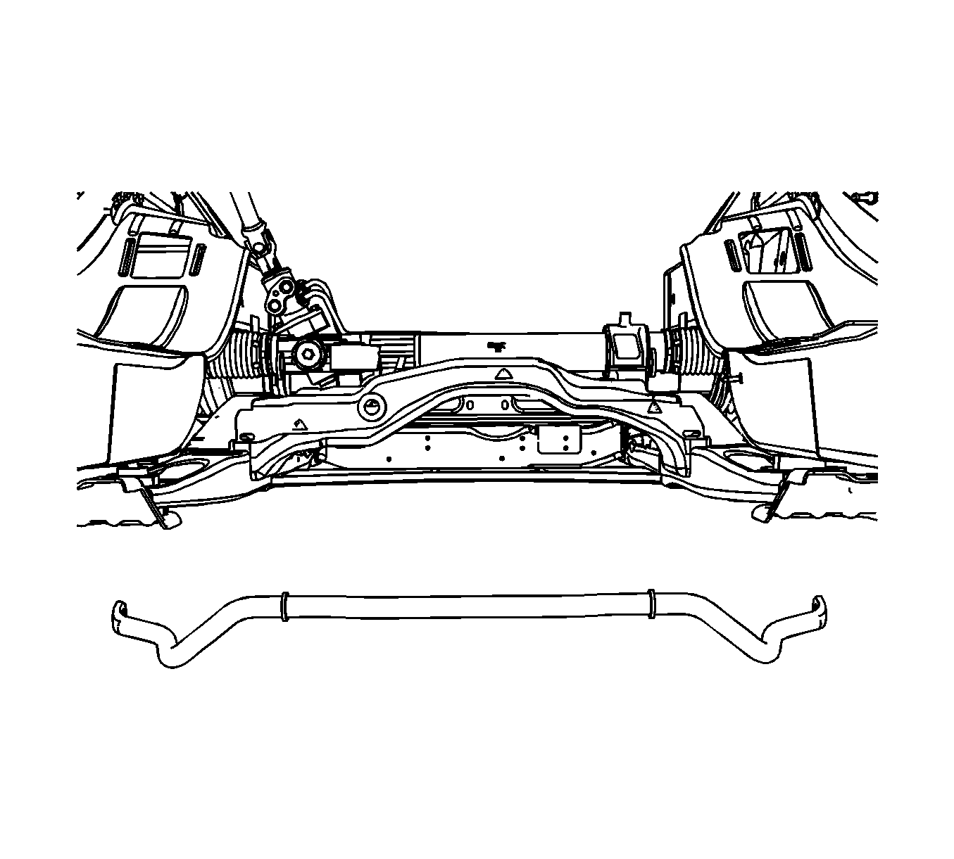
Note: It maybe necessary to maneuver the stabilizer shaft in such a way to remove it from the front cradle.
Installation Procedure
- Position the stabilizer shaft on the frame.
- Install the left and right stabilizer shaft insulators and brackets. Refer to Stabilizer Shaft Insulator Replacement.
- Install the stabilizer shaft links to the stabilizer shaft. Refer to Stabilizer Shaft Link Replacement.
- Using the jack stands, raise the front cradle into position.
- Tighten the front frame (2) bolts.
- Tighten the front frame reinforcement mounting bolts (1). Left side shown, right side similar.
- Tighten the rear frame mounting bolts (1). Left side shown, right side similar.
- Tighten the rear reinforcement bolts. Left side shown, right side similar.
- Remove the adjustable jack stands.
- Install the bolt from the intermediate shaft bracket to the front cradle. Refer to Intermediate Drive Shaft Replacement.
- Install the outer tie rod ends to the knuckle. Refer to Steering Linkage Outer Tie Rod Replacement.
- Install the rear propeller shaft, if equipped. Refer to Propeller Shaft Replacement.
- Install the front tires and wheels. Refer to Tire and Wheel Removal and Installation.
- Remove the support and lower the vehicle.

Caution: Refer to Fastener Caution in the Preface section.

Tighten
Tighten the frame to body bolts to 100 N·m (74 lb ft) plus 90 degrees.
Tighten
Tighten the reinforcement bolts to 50 N·m (37 lb ft).

Tighten
Tighten the frame to body bolts to 100 N·m (74 lb ft) plus 90 degrees.

Tighten
Tighten the reinforcement bolts to 50 N·m (37 lb ft).
